
2012
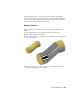


Table Of Contents
- Contents
- Get Information
- The User Interface
- Start and Save Drawings
- Control the Drawing Views
- Organize Drawings and Layouts
- Create and Modify Objects
- Control the Properties of Objects
- Use Precision Tools
- Work with the User Coordinate System (UCS)
- Enter Coordinates to Specify Points
- Use Dynamic Input
- Snap to Locations on Objects (Object Snaps)
- Restrict Cursor Movement
- Combine or Offset Points and Coordinates
- Specify Distances
- Extract Geometric Information from Objects
- Use a Calculator
- Create Objects
- Select and Modify Objects
- Select Objects
- Correct Mistakes
- Erase Objects
- Cut, Copy, and Paste with the Clipboard
- Modify Objects
- Add Constraints to Geometry
- Define and Reference Blocks
- Work with 3D Models
- Create 3D Models
- Overview of 3D Modeling
- Create Solids and Surfaces from Lines and Curves
- Create Solids
- Create Surfaces
- Create Meshes
- Create Wireframe Models
- Add 3D Thickness to Objects
- Modify 3D Models
- Create Sections and Drawings from 3D Models
- Create 3D Models
- Annotate Drawings
- Work with Annotations
- Overview of Annotations
- Scale Annotations
- Overview of Scaling Annotations
- Set Annotation Scale
- Create Annotative Objects
- Display Annotative Objects
- Add and Modify Scale Representations
- Set Orientation for Annotations
- Hatches, Fills, and Wipeouts
- Notes and Labels
- Tables
- Dimensions and Tolerances
- Understand Basic Concepts of Dimensioning
- Use Dimension Styles
- Set the Scale for Dimensions
- Create Dimensions
- Modify Existing Dimensions
- Add Geometric Tolerances
- Work with Annotations
- Plot and Publish Drawings
- Specify Settings for Plotting
- Save Plot Settings as Named Page Setups
- Reuse Named Page Setups
- Specify Page Setup Settings
- Select a Printer or Plotter for a Layout
- Select a Paper Size for a Layout
- Determine the Drawing Orientation of a Layout
- Set the Plot Area of a Layout
- Adjust the Plot Offset of a Layout
- Set the Plot Scale for a Layout
- Set the Lineweight Scale for a Layout
- Select a Plot Style Table for a Layout
- Set Shaded Viewport and Plot Options for a Layout
- Print or Plot Drawings
- Overview of Plotting
- Use a Page Setup to Specify Plot Settings
- Select a Printer or Plotter
- Specify the Area to Plot
- Set Paper Size
- Position the Drawing on the Paper
- Control How Objects Are Plotted
- Preview a Plot
- Plot Files to Other Formats
- Publish Drawings
- Specify Settings for Plotting
- Share Data Between Files
- Reference Other Drawing Files
- Work with Data in Other Formats
- Collaborate with Others
- Render Drawings
- Draw 2D Isometric Views
- Add Lighting to Your Model
- Materials and Textures
- Render 3D Objects for Realism
- Glossary
- Index
Use Grip Editing with Mesh
Grips, as described in
Use Grips to Edit 3D Solids and Surfaces (page 458), are
not available with meshes. However, you can manipulate the entire mesh
model or individual subobjects using the following methods:
Subobject selection and editing. Select faces, edges, and vertices the
same way you select 3D solid subobjects. Press and hold Ctrl while selecting
a subobject. The subobject highlighting indicates what is selected. Press
and hold Shift and click again to remove the selection from a subobject.
By turning on the Subobject Selection Filter, you can restrict selection to
a specific subobject, which you can select without pressing and holding
Ctrl. See
Select 3D Subobjects (page 455).
Gizmo editing.When you select a mesh object or subobject, the 3D Move,
Rotate, or Scale gizmo is displayed automatically. (You can set which gizmo
is displayed by default.) Use these gizmos to modify the selection uniformly,
or along a specified plane or axis. Form more information, see
Use Gizmos
to Modify Objects
(page 443).
Because dense meshes can be difficult to work with, you can change settings
to improve the display and behavior of grips.
Set the subobject selection filter to select only faces, edges, or
vertices: Set the DEFAULTGIZMO system variable or use the shortcut
menu.
Set whether a grip on a face, edge, or vertex is active
immediately when you select the subobject: Set the
GRIPSUBOBJMODE system variable.
See also:
Use Grips to Edit 3D Solids and Surfaces (page 458)
Use Gizmos to Modify Objects (page 443)
Change Mesh Smoothness Levels
Increase the roundness of mesh objects by increasing the smoothness levels.
Mesh objects are made up of multiple subdivisions, or tessellations, which
define the editable faces. Each face consists of underlying facets. When you
increase smoothness, you increase the number of facets to provide a smoother,
more rounded look.
Modify 3D Models | 503