
2012
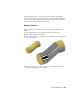


Table Of Contents
- Contents
- Get Information
- The User Interface
- Start and Save Drawings
- Control the Drawing Views
- Organize Drawings and Layouts
- Create and Modify Objects
- Control the Properties of Objects
- Use Precision Tools
- Work with the User Coordinate System (UCS)
- Enter Coordinates to Specify Points
- Use Dynamic Input
- Snap to Locations on Objects (Object Snaps)
- Restrict Cursor Movement
- Combine or Offset Points and Coordinates
- Specify Distances
- Extract Geometric Information from Objects
- Use a Calculator
- Create Objects
- Select and Modify Objects
- Select Objects
- Correct Mistakes
- Erase Objects
- Cut, Copy, and Paste with the Clipboard
- Modify Objects
- Add Constraints to Geometry
- Define and Reference Blocks
- Work with 3D Models
- Create 3D Models
- Overview of 3D Modeling
- Create Solids and Surfaces from Lines and Curves
- Create Solids
- Create Surfaces
- Create Meshes
- Create Wireframe Models
- Add 3D Thickness to Objects
- Modify 3D Models
- Create Sections and Drawings from 3D Models
- Create 3D Models
- Annotate Drawings
- Work with Annotations
- Overview of Annotations
- Scale Annotations
- Overview of Scaling Annotations
- Set Annotation Scale
- Create Annotative Objects
- Display Annotative Objects
- Add and Modify Scale Representations
- Set Orientation for Annotations
- Hatches, Fills, and Wipeouts
- Notes and Labels
- Tables
- Dimensions and Tolerances
- Understand Basic Concepts of Dimensioning
- Use Dimension Styles
- Set the Scale for Dimensions
- Create Dimensions
- Modify Existing Dimensions
- Add Geometric Tolerances
- Work with Annotations
- Plot and Publish Drawings
- Specify Settings for Plotting
- Save Plot Settings as Named Page Setups
- Reuse Named Page Setups
- Specify Page Setup Settings
- Select a Printer or Plotter for a Layout
- Select a Paper Size for a Layout
- Determine the Drawing Orientation of a Layout
- Set the Plot Area of a Layout
- Adjust the Plot Offset of a Layout
- Set the Plot Scale for a Layout
- Set the Lineweight Scale for a Layout
- Select a Plot Style Table for a Layout
- Set Shaded Viewport and Plot Options for a Layout
- Print or Plot Drawings
- Overview of Plotting
- Use a Page Setup to Specify Plot Settings
- Select a Printer or Plotter
- Specify the Area to Plot
- Set Paper Size
- Position the Drawing on the Paper
- Control How Objects Are Plotted
- Preview a Plot
- Plot Files to Other Formats
- Publish Drawings
- Specify Settings for Plotting
- Share Data Between Files
- Reference Other Drawing Files
- Work with Data in Other Formats
- Collaborate with Others
- Render Drawings
- Draw 2D Isometric Views
- Add Lighting to Your Model
- Materials and Textures
- Render 3D Objects for Realism
- Glossary
- Index
About Mesh Facets
Mesh faces have underlying structures, known as facets. The density of the
facet grid corresponds to the smoothness of the mesh. As the smoothness
level is increased, the density of the underlying facet grid also increases. When
you want to confine detailed mesh editing to a smaller area, you can convert
facets to editable faces by using refinement.
Unlike faces, facets cannot be individually modified. However, you can make
them more visible by modifying the VSLIGHTINGQUALITY system variable.
About Mesh Modeling
You can work with mesh objects in the following ways:
Add smoothness. Increase or decrease smoothness levels to round the
overall shape of the model. The underlying density of the mesh facet grid
increases as the mesh object smoothness level increases
(MESHSMOOTHMORE, MESHSMOOTHLESS).
Refine the object to reset the baseline smoothness level. Refine a
mesh object to convert the underlying facet grid to editable faces.
Refinement also resets the lowest level of smoothness that can be applied
to the object (MESHREFINE).
Refine a face. Restrict the refinement to a specific mesh face. This method
avoids resetting the smoothness baseline.
Crease an edge. Remove the smoothness from specified edges. You can
also remove an existing crease (MESHCREASE).
Split or merge faces.Divide an existing face into separate components
along a specified path. Merge two or more faces to create a single face
(MESHSPLITMESHMERGE).
Collapse vertices. Alter the mesh model by collapsing the vertices of
adjacent faces to a single point (MESHCOLLAPSE.
Spin edges.Spin the shared edge of adjacent triangular faces to alter the
shapes and orientation of the faces (MESHSPIN).
Extrude a face.Extend a specified face by extruding it into 3D space.
Unlike 3D solid extrusion, a mesh extrusion does not create a separate
object (MESHEXTRUDE).
Repair holes.Close a gap between faces by selecting the surrounding
edges. Holes in mesh objects can prevent you from converting a mesh
object to a solid object (MESHCAP).
502 | Chapter 8 Work with 3D Models