
2012
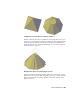
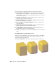


Table Of Contents
- Contents
- Get Information
- The User Interface
- Start and Save Drawings
- Control the Drawing Views
- Organize Drawings and Layouts
- Create and Modify Objects
- Control the Properties of Objects
- Use Precision Tools
- Work with the User Coordinate System (UCS)
- Enter Coordinates to Specify Points
- Use Dynamic Input
- Snap to Locations on Objects (Object Snaps)
- Restrict Cursor Movement
- Combine or Offset Points and Coordinates
- Specify Distances
- Extract Geometric Information from Objects
- Use a Calculator
- Create Objects
- Select and Modify Objects
- Select Objects
- Correct Mistakes
- Erase Objects
- Cut, Copy, and Paste with the Clipboard
- Modify Objects
- Add Constraints to Geometry
- Define and Reference Blocks
- Work with 3D Models
- Create 3D Models
- Overview of 3D Modeling
- Create Solids and Surfaces from Lines and Curves
- Create Solids
- Create Surfaces
- Create Meshes
- Create Wireframe Models
- Add 3D Thickness to Objects
- Modify 3D Models
- Create Sections and Drawings from 3D Models
- Create 3D Models
- Annotate Drawings
- Work with Annotations
- Overview of Annotations
- Scale Annotations
- Overview of Scaling Annotations
- Set Annotation Scale
- Create Annotative Objects
- Display Annotative Objects
- Add and Modify Scale Representations
- Set Orientation for Annotations
- Hatches, Fills, and Wipeouts
- Notes and Labels
- Tables
- Dimensions and Tolerances
- Understand Basic Concepts of Dimensioning
- Use Dimension Styles
- Set the Scale for Dimensions
- Create Dimensions
- Modify Existing Dimensions
- Add Geometric Tolerances
- Work with Annotations
- Plot and Publish Drawings
- Specify Settings for Plotting
- Save Plot Settings as Named Page Setups
- Reuse Named Page Setups
- Specify Page Setup Settings
- Select a Printer or Plotter for a Layout
- Select a Paper Size for a Layout
- Determine the Drawing Orientation of a Layout
- Set the Plot Area of a Layout
- Adjust the Plot Offset of a Layout
- Set the Plot Scale for a Layout
- Set the Lineweight Scale for a Layout
- Select a Plot Style Table for a Layout
- Set Shaded Viewport and Plot Options for a Layout
- Print or Plot Drawings
- Overview of Plotting
- Use a Page Setup to Specify Plot Settings
- Select a Printer or Plotter
- Specify the Area to Plot
- Set Paper Size
- Position the Drawing on the Paper
- Control How Objects Are Plotted
- Preview a Plot
- Plot Files to Other Formats
- Publish Drawings
- Specify Settings for Plotting
- Share Data Between Files
- Reference Other Drawing Files
- Work with Data in Other Formats
- Collaborate with Others
- Render Drawings
- Draw 2D Isometric Views
- Add Lighting to Your Model
- Materials and Textures
- Render 3D Objects for Realism
- Glossary
- Index
The Properties Inspector indicates if the surface contains any trimmed edges.
Projecting Geometry onto Surfaces, Solids, and Regions
Similar to projecting a movie onto a screen, you can project geometry onto
3D solids, surfaces, and regions from different directions to create trimming
edges. The PROJECTGEOMETRY command creates a duplicate curve on the
object that you can move and edit. You can also trim against 2D curves that
do not actually touch the surface, but that appear to intersect the object in
the current view.
Use the SURFACEAUTOTRIM system variable to automatically trim a surface
when you project geometry onto it.
Options for Projecting Geometry
Project geometry from 3 different angles: the Z axis of the current UCS, the
current view, or a path between two points.
Project to UCS - Projects the geometry along the positive or negative Z
axis of the current UCS.
Project to View - Projects the geometry based on the current view.
Project to Two Points - Projects the geometry along a path between
two points.
Extend a Surface
Create a new surface by extending it to meet the edge of another object or by
specifying an extension length.
There are two types of extend surfaces: merge and append. The merge surface
is a continuation of the surface with no seam. The append surface extends the
surface by adding a second surface with a seam. Because it creates a seam,
append surfaces have
continuity and bulge magnitude (page 396) properties.
For both surface types, use the Properties Inspector to change the length or
to derive the length from a mathematical expression.
492 | Chapter 8 Work with 3D Models