
2012


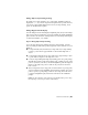

Table Of Contents
- Contents
- Get Information
- The User Interface
- Start and Save Drawings
- Control the Drawing Views
- Organize Drawings and Layouts
- Create and Modify Objects
- Control the Properties of Objects
- Use Precision Tools
- Work with the User Coordinate System (UCS)
- Enter Coordinates to Specify Points
- Use Dynamic Input
- Snap to Locations on Objects (Object Snaps)
- Restrict Cursor Movement
- Combine or Offset Points and Coordinates
- Specify Distances
- Extract Geometric Information from Objects
- Use a Calculator
- Create Objects
- Select and Modify Objects
- Select Objects
- Correct Mistakes
- Erase Objects
- Cut, Copy, and Paste with the Clipboard
- Modify Objects
- Add Constraints to Geometry
- Define and Reference Blocks
- Work with 3D Models
- Create 3D Models
- Overview of 3D Modeling
- Create Solids and Surfaces from Lines and Curves
- Create Solids
- Create Surfaces
- Create Meshes
- Create Wireframe Models
- Add 3D Thickness to Objects
- Modify 3D Models
- Create Sections and Drawings from 3D Models
- Create 3D Models
- Annotate Drawings
- Work with Annotations
- Overview of Annotations
- Scale Annotations
- Overview of Scaling Annotations
- Set Annotation Scale
- Create Annotative Objects
- Display Annotative Objects
- Add and Modify Scale Representations
- Set Orientation for Annotations
- Hatches, Fills, and Wipeouts
- Notes and Labels
- Tables
- Dimensions and Tolerances
- Understand Basic Concepts of Dimensioning
- Use Dimension Styles
- Set the Scale for Dimensions
- Create Dimensions
- Modify Existing Dimensions
- Add Geometric Tolerances
- Work with Annotations
- Plot and Publish Drawings
- Specify Settings for Plotting
- Save Plot Settings as Named Page Setups
- Reuse Named Page Setups
- Specify Page Setup Settings
- Select a Printer or Plotter for a Layout
- Select a Paper Size for a Layout
- Determine the Drawing Orientation of a Layout
- Set the Plot Area of a Layout
- Adjust the Plot Offset of a Layout
- Set the Plot Scale for a Layout
- Set the Lineweight Scale for a Layout
- Select a Plot Style Table for a Layout
- Set Shaded Viewport and Plot Options for a Layout
- Print or Plot Drawings
- Overview of Plotting
- Use a Page Setup to Specify Plot Settings
- Select a Printer or Plotter
- Specify the Area to Plot
- Set Paper Size
- Position the Drawing on the Paper
- Control How Objects Are Plotted
- Preview a Plot
- Plot Files to Other Formats
- Publish Drawings
- Specify Settings for Plotting
- Share Data Between Files
- Reference Other Drawing Files
- Work with Data in Other Formats
- Collaborate with Others
- Render Drawings
- Draw 2D Isometric Views
- Add Lighting to Your Model
- Materials and Textures
- Render 3D Objects for Realism
- Glossary
- Index

Polar angles are relative to the orientation of the current user coordinate
system (UCS) and the setting for the base angle convention in a drawing. The
angle base direction is set in the Drawing Units dialog box (UNITS).
Use PolarSnap
™
to snap to specified distances along the alignment path. For
example, in the following illustration you draw a two-unit line from point 1
to point 2, and then draw a two-unit line to point 3 at a 45-degree angle to
the line. If you turn on the 45-degree polar angle increment, an alignment
path and tooltip are displayed when your cursor crosses the 0 or 45-degree
angle. The alignment path and tooltip disappear when you move the cursor
away from the angle.
As you move your cursor, alignment paths and tooltips are displayed when
you move the cursor near polar angles. The default angle measurement is 90
degrees. Use the alignment path and tooltip to draw your object. You can use
polar tracking with Intersection and Apparent Intersection object snaps to
find where a polar alignment path intersects another object.
NOTE
Ortho mode and polar tracking cannot be on at the same time. Turning on
polar tracking turns off Ortho mode. Similarly, PolarSnap and grid snap cannot
be on at the same time. Turning on PolarSnap turns off grid snap.
Specify Polar Angles (Polar Tracking)
You can use polar tracking to track along polar angle increments of 90, 60,
45, 30, 22.5, 18, 15, 10, and 5 degrees, or you can specify other angles. The
following illustration shows the alignment paths displayed as you move your
cursor 90 degrees with the polar angle increment set to 30 degrees.
Use Precision Tools | 177