
2011


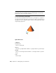

Table Of Contents
- Contents
- Get Information
- The User Interface
- Start and Save Drawings
- Control the Drawing Views
- Organize Drawings and Layouts
- Create and Modify Objects
- Control the Properties of Objects
- Use Precision Tools
- Use Coordinates and Coordinate Systems (UCS)
- Use Dynamic Input
- Snap to Locations on Objects (Object Snaps)
- Restrict Cursor Movement
- Combine or Offset Points and Coordinates
- Specify Distances
- Extract Geometric Information from Objects
- Use a Calculator
- Draw Geometric Objects
- Change Existing Objects
- Select Objects
- Correct Mistakes
- Erase Objects
- Cut, Copy, and Paste with the Clipboard
- Modify Objects
- Modify Complex Objects
- Add Constraints to Geometry
- Define and Reference Blocks
- Work with 3D Models
- Create 3D Models
- Overview of 3D Modeling
- Create Solids and Surfaces from Lines and Curves
- Create Solids
- Create Surfaces
- Create Meshes
- Create Wireframe Models
- Add 3D Thickness to Objects
- Modify 3D Models
- Create Sections and 2D Drawings from 3D Models
- Create 3D Models
- Annotate Drawings
- Work with Annotations
- Hatches, Fills, and Wipeouts
- Notes and Labels
- Tables
- Dimensions and Tolerances
- Understand Basic Concepts of Dimensioning
- Use Dimension Styles
- Set the Scale for Dimensions
- Create Dimensions
- Modify Existing Dimensions
- Add Geometric Tolerances
- Plot and Publish Drawings
- Specify Settings for Plotting
- Save Plot Settings as Named Page Setups
- Reuse Named Page Setups
- Specify Page Setup Settings
- Select a Printer or Plotter for a Layout
- Select a Paper Size for a Layout
- Determine the Drawing Orientation of a Layout
- Set the Plot Area of a Layout
- Adjust the Plot Offset of a Layout
- Set the Plot Scale for a Layout
- Set the Lineweight Scale for a Layout
- Select a Plot Style Table for a Layout
- Set Shaded Viewport and Plot Options for a Layout
- Print or Plot Drawings
- Overview of Plotting
- Use a Page Setup to Specify Plot Settings
- Select a Printer or Plotter
- Specify the Area to Plot
- Set Paper Size
- Position the Drawing on the Paper
- Control How Objects Are Plotted
- Preview a Plot
- Plot Files to Other Formats
- Specify Settings for Plotting
- Share Data Between Files
- Reference Other Drawing Files
- Work with Data in Other Formats
- Collaborate with Others
- Render Drawings
- Draw 2D Isometric Views
- Add Lighting to Your Model
- Materials and Textures
- Render 3D Objects for Realism
- Glossary
- Index
way to assign a shape to the light. The shape affects the rendering and shadows
in the same way that a panel light casts different light than a tube light in the
real world.
The Shape Property
The Shape property is available in the Properties Inspector. Under
ShadowDetail, there is a Type property. Whether the Shape property is
displayed depends on the Type property that is selected.
The following types are available: Soft (shadow) map, Sharp (default), Soft
(sampled). By selecting the Soft (sampled) option, the Shape property becomes
available.
The available shapes depend on the type of light. You can select the Type
property for the light distribution under the General panel in the Lighting
category. If Spotlight and Soft (sampled) are selected, then the Shape types
available are Rectangular and Disk. If Point and Soft (sampled) are selected,
then the following shapes are available: Linear, Rectangular, Disk, Cylinder,
and Sphere. If Web and Soft (sampled) are selected, then the following shapes
are available: Linear, Rectangular, Disk, Cylinder, and Sphere. You can use the
samples property on the area light to control the trade-off between rendering
time and shadow accuracy.
The Visible in Render option is also displayed under ShadowDetail and controls
the visibility of the shape when the scene is rendered.
Adjust and Manipulate Lights
You can add point lights, spotlights, and distant lights and set the location
and properties of each.
Control the Display of Lights
The display of lights can be turned on and off in the drawing.
A light glyph is a graphic representation of a light. Point lights and spotlights
can be placed in a drawing with a light glyph. Distant lights, such as sunlight,
are not represented with a light glyph.
The display of lights can be controlled several ways. On the Command Line,
the LIGHTGLYPHDISPLAY system variable controls the display of light glyphs
in the drawing.
978 | Chapter 36 Add Lighting to Your Model