
2011


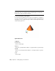

Table Of Contents
- Contents
- Get Information
- The User Interface
- Start and Save Drawings
- Control the Drawing Views
- Organize Drawings and Layouts
- Create and Modify Objects
- Control the Properties of Objects
- Use Precision Tools
- Use Coordinates and Coordinate Systems (UCS)
- Use Dynamic Input
- Snap to Locations on Objects (Object Snaps)
- Restrict Cursor Movement
- Combine or Offset Points and Coordinates
- Specify Distances
- Extract Geometric Information from Objects
- Use a Calculator
- Draw Geometric Objects
- Change Existing Objects
- Select Objects
- Correct Mistakes
- Erase Objects
- Cut, Copy, and Paste with the Clipboard
- Modify Objects
- Modify Complex Objects
- Add Constraints to Geometry
- Define and Reference Blocks
- Work with 3D Models
- Create 3D Models
- Overview of 3D Modeling
- Create Solids and Surfaces from Lines and Curves
- Create Solids
- Create Surfaces
- Create Meshes
- Create Wireframe Models
- Add 3D Thickness to Objects
- Modify 3D Models
- Create Sections and 2D Drawings from 3D Models
- Create 3D Models
- Annotate Drawings
- Work with Annotations
- Hatches, Fills, and Wipeouts
- Notes and Labels
- Tables
- Dimensions and Tolerances
- Understand Basic Concepts of Dimensioning
- Use Dimension Styles
- Set the Scale for Dimensions
- Create Dimensions
- Modify Existing Dimensions
- Add Geometric Tolerances
- Plot and Publish Drawings
- Specify Settings for Plotting
- Save Plot Settings as Named Page Setups
- Reuse Named Page Setups
- Specify Page Setup Settings
- Select a Printer or Plotter for a Layout
- Select a Paper Size for a Layout
- Determine the Drawing Orientation of a Layout
- Set the Plot Area of a Layout
- Adjust the Plot Offset of a Layout
- Set the Plot Scale for a Layout
- Set the Lineweight Scale for a Layout
- Select a Plot Style Table for a Layout
- Set Shaded Viewport and Plot Options for a Layout
- Print or Plot Drawings
- Overview of Plotting
- Use a Page Setup to Specify Plot Settings
- Select a Printer or Plotter
- Specify the Area to Plot
- Set Paper Size
- Position the Drawing on the Paper
- Control How Objects Are Plotted
- Preview a Plot
- Plot Files to Other Formats
- Specify Settings for Plotting
- Share Data Between Files
- Reference Other Drawing Files
- Work with Data in Other Formats
- Collaborate with Others
- Render Drawings
- Draw 2D Isometric Views
- Add Lighting to Your Model
- Materials and Textures
- Render 3D Objects for Realism
- Glossary
- Index

Distant Lights in Standard Lighting Workflow
A distant light emits uniform parallel light rays in one direction only. You
specify a FROM point and a TO point anywhere in the viewport to define the
direction of the light. Spotlights and point lights are each represented by a
different light glyph. Distant lights are not represented by glyphs in the
drawing because they do not have a discrete position and affect the entire
scene.
The intensity of a distant light does not diminish over distance; it is as bright
at each face it strikes as it is at the source. Distant lights are useful for lighting
objects or for lighting a backdrop uniformly.
NOTE It is recommended that you do not use distant lights in blocks.
Distant Lights in Photometric Workflow
Distant lights are not physically accurate. It is recommended that you do not
use them in a photometric workflow.
Quick Reference
Commands
DISTANTLIGHT
Creates a distant light.
System Variables
LIGHTINGUNITS
Controls whether generic or photometric lights are used, and specifies the
lighting units for the drawing.
Assigning a Shape to a Light
Assigning a shape to a light modifies the illumination of a scene.
Area and Linear Lights
The Area parameter on the light is a property of a light. Just as a light can have
a color, it can also be assigned a shape. For example, you can shape it like a
rectangle so that it acts like panel lighting in a ceiling. Or you can shape it
like a line, so it acts like a narrow fluorescent light tube. The area light is a
Assigning a Shape to a Light | 977