
2011


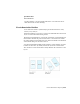


Table Of Contents
- Contents
- Get Information
- The User Interface
- Start and Save Drawings
- Control the Drawing Views
- Organize Drawings and Layouts
- Create and Modify Objects
- Control the Properties of Objects
- Use Precision Tools
- Use Coordinates and Coordinate Systems (UCS)
- Use Dynamic Input
- Snap to Locations on Objects (Object Snaps)
- Restrict Cursor Movement
- Combine or Offset Points and Coordinates
- Specify Distances
- Extract Geometric Information from Objects
- Use a Calculator
- Draw Geometric Objects
- Change Existing Objects
- Select Objects
- Correct Mistakes
- Erase Objects
- Cut, Copy, and Paste with the Clipboard
- Modify Objects
- Modify Complex Objects
- Add Constraints to Geometry
- Define and Reference Blocks
- Work with 3D Models
- Create 3D Models
- Overview of 3D Modeling
- Create Solids and Surfaces from Lines and Curves
- Create Solids
- Create Surfaces
- Create Meshes
- Create Wireframe Models
- Add 3D Thickness to Objects
- Modify 3D Models
- Create Sections and 2D Drawings from 3D Models
- Create 3D Models
- Annotate Drawings
- Work with Annotations
- Hatches, Fills, and Wipeouts
- Notes and Labels
- Tables
- Dimensions and Tolerances
- Understand Basic Concepts of Dimensioning
- Use Dimension Styles
- Set the Scale for Dimensions
- Create Dimensions
- Modify Existing Dimensions
- Add Geometric Tolerances
- Plot and Publish Drawings
- Specify Settings for Plotting
- Save Plot Settings as Named Page Setups
- Reuse Named Page Setups
- Specify Page Setup Settings
- Select a Printer or Plotter for a Layout
- Select a Paper Size for a Layout
- Determine the Drawing Orientation of a Layout
- Set the Plot Area of a Layout
- Adjust the Plot Offset of a Layout
- Set the Plot Scale for a Layout
- Set the Lineweight Scale for a Layout
- Select a Plot Style Table for a Layout
- Set Shaded Viewport and Plot Options for a Layout
- Print or Plot Drawings
- Overview of Plotting
- Use a Page Setup to Specify Plot Settings
- Select a Printer or Plotter
- Specify the Area to Plot
- Set Paper Size
- Position the Drawing on the Paper
- Control How Objects Are Plotted
- Preview a Plot
- Plot Files to Other Formats
- Specify Settings for Plotting
- Share Data Between Files
- Reference Other Drawing Files
- Work with Data in Other Formats
- Collaborate with Others
- Render Drawings
- Draw 2D Isometric Views
- Add Lighting to Your Model
- Materials and Textures
- Render 3D Objects for Realism
- Glossary
- Index
If an object supports more than one annotation scale, the object will display
at the current scale.
When the MSLTSCALE system variable is set to 1 (default), linetypes displayed
on the model tab are scaled by the annotation scale
See also:
■ The Application Menu
Quick Reference
System Variables
ANNOALLVISIBLE
Hides or displays annotative objects that do not support the current
annotation scale.
MSLTSCALE
Scales linetypes displayed on the model tab by the annotation scale.
SELECTIONANNODISPLAY
Controls whether alternate scale representations are temporarily displayed
in a dimmed state when an annotative object is selected.
Add and Modify Scale Representations
When you create an object in your drawing, it supports one : the annotation
scale that was current when you created the object. You can update annotative
objects to support additional annotation scales.
When you update an annotative object to support additional scales, you add
additional to the object.
For example, if an annotative multileader supports two annotation scales, it
has two scale representations.
When you select an annotative object, grips are displayed on the scale
representation that supports the current annotation scale. You can use these
grips to manipulate the current scale representation. All other scale
representations of the object are displayed in a dimmed state when the
SELECTIONANNODISPLAY system variable is set to 1 (default).
Add and Modify Scale Representations | 671