
2011


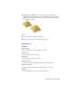


Table Of Contents
- Contents
- Get Information
- The User Interface
- Start and Save Drawings
- Control the Drawing Views
- Organize Drawings and Layouts
- Create and Modify Objects
- Control the Properties of Objects
- Use Precision Tools
- Use Coordinates and Coordinate Systems (UCS)
- Use Dynamic Input
- Snap to Locations on Objects (Object Snaps)
- Restrict Cursor Movement
- Combine or Offset Points and Coordinates
- Specify Distances
- Extract Geometric Information from Objects
- Use a Calculator
- Draw Geometric Objects
- Change Existing Objects
- Select Objects
- Correct Mistakes
- Erase Objects
- Cut, Copy, and Paste with the Clipboard
- Modify Objects
- Modify Complex Objects
- Add Constraints to Geometry
- Define and Reference Blocks
- Work with 3D Models
- Create 3D Models
- Overview of 3D Modeling
- Create Solids and Surfaces from Lines and Curves
- Create Solids
- Create Surfaces
- Create Meshes
- Create Wireframe Models
- Add 3D Thickness to Objects
- Modify 3D Models
- Create Sections and 2D Drawings from 3D Models
- Create 3D Models
- Annotate Drawings
- Work with Annotations
- Hatches, Fills, and Wipeouts
- Notes and Labels
- Tables
- Dimensions and Tolerances
- Understand Basic Concepts of Dimensioning
- Use Dimension Styles
- Set the Scale for Dimensions
- Create Dimensions
- Modify Existing Dimensions
- Add Geometric Tolerances
- Plot and Publish Drawings
- Specify Settings for Plotting
- Save Plot Settings as Named Page Setups
- Reuse Named Page Setups
- Specify Page Setup Settings
- Select a Printer or Plotter for a Layout
- Select a Paper Size for a Layout
- Determine the Drawing Orientation of a Layout
- Set the Plot Area of a Layout
- Adjust the Plot Offset of a Layout
- Set the Plot Scale for a Layout
- Set the Lineweight Scale for a Layout
- Select a Plot Style Table for a Layout
- Set Shaded Viewport and Plot Options for a Layout
- Print or Plot Drawings
- Overview of Plotting
- Use a Page Setup to Specify Plot Settings
- Select a Printer or Plotter
- Specify the Area to Plot
- Set Paper Size
- Position the Drawing on the Paper
- Control How Objects Are Plotted
- Preview a Plot
- Plot Files to Other Formats
- Specify Settings for Plotting
- Share Data Between Files
- Reference Other Drawing Files
- Work with Data in Other Formats
- Collaborate with Others
- Render Drawings
- Draw 2D Isometric Views
- Add Lighting to Your Model
- Materials and Textures
- Render 3D Objects for Realism
- Glossary
- Index

If removal of a mesh face creates a gap, the mesh object is not “watertight.”
It can be converted to a surface object, but not to a 3D solid object.
Close Gaps in Mesh Objects
If a mesh object is not watertight due to gaps, or holes, in the mesh, you can
make it watertight by closing the holes. The cap, or new face, spans the
boundary formed by the mesh edges that you specify (MESHCAP).
This process works best when all edges are on the same plane. The edges you
select as boundaries cannot be shared by two faces. For example, you cannot
close the center hole in a mesh torus.
NOTE You can sometimes close gaps in mesh by smoothing the object, by using
MESHCOLLAPSE, or by splitting adjacent faces (MESHSPLIT).
See also:
■ Tips for Working with Mesh on page 627
Quick Reference
Commands
ERASE
Removes objects from a drawing.
MESHCAP
Creates a mesh face that connects open edges.
Tips for Working with Mesh
Learn some best practices for working with mesh models.
Tips for Working with Mesh | 627