
2011


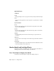
Table Of Contents
- Contents
- Get Information
- The User Interface
- Start and Save Drawings
- Control the Drawing Views
- Organize Drawings and Layouts
- Create and Modify Objects
- Control the Properties of Objects
- Use Precision Tools
- Use Coordinates and Coordinate Systems (UCS)
- Use Dynamic Input
- Snap to Locations on Objects (Object Snaps)
- Restrict Cursor Movement
- Combine or Offset Points and Coordinates
- Specify Distances
- Extract Geometric Information from Objects
- Use a Calculator
- Draw Geometric Objects
- Change Existing Objects
- Select Objects
- Correct Mistakes
- Erase Objects
- Cut, Copy, and Paste with the Clipboard
- Modify Objects
- Modify Complex Objects
- Add Constraints to Geometry
- Define and Reference Blocks
- Work with 3D Models
- Create 3D Models
- Overview of 3D Modeling
- Create Solids and Surfaces from Lines and Curves
- Create Solids
- Create Surfaces
- Create Meshes
- Create Wireframe Models
- Add 3D Thickness to Objects
- Modify 3D Models
- Create Sections and 2D Drawings from 3D Models
- Create 3D Models
- Annotate Drawings
- Work with Annotations
- Hatches, Fills, and Wipeouts
- Notes and Labels
- Tables
- Dimensions and Tolerances
- Understand Basic Concepts of Dimensioning
- Use Dimension Styles
- Set the Scale for Dimensions
- Create Dimensions
- Modify Existing Dimensions
- Add Geometric Tolerances
- Plot and Publish Drawings
- Specify Settings for Plotting
- Save Plot Settings as Named Page Setups
- Reuse Named Page Setups
- Specify Page Setup Settings
- Select a Printer or Plotter for a Layout
- Select a Paper Size for a Layout
- Determine the Drawing Orientation of a Layout
- Set the Plot Area of a Layout
- Adjust the Plot Offset of a Layout
- Set the Plot Scale for a Layout
- Set the Lineweight Scale for a Layout
- Select a Plot Style Table for a Layout
- Set Shaded Viewport and Plot Options for a Layout
- Print or Plot Drawings
- Overview of Plotting
- Use a Page Setup to Specify Plot Settings
- Select a Printer or Plotter
- Specify the Area to Plot
- Set Paper Size
- Position the Drawing on the Paper
- Control How Objects Are Plotted
- Preview a Plot
- Plot Files to Other Formats
- Specify Settings for Plotting
- Share Data Between Files
- Reference Other Drawing Files
- Work with Data in Other Formats
- Collaborate with Others
- Render Drawings
- Draw 2D Isometric Views
- Add Lighting to Your Model
- Materials and Textures
- Render 3D Objects for Realism
- Glossary
- Index

options: SW (southwest) Isometric, SE (southeast) Isometric, NE (northeast)
Isometric, and NW (northwest) Isometric.
To understand how the isometric views work, imagine you are looking down
at the top of a box. If you move toward the lower-left corner of the box, you
are viewing the box from the SW Isometric View. If you move toward the
upper-right corner of the box, you are viewing it from NE Isometric View.
Quick Reference
Commands
VIEW
Saves and restores named model space views, layout views, and preset views.
Define a 3D View with Coordinate Values or Angles
You can define a viewing direction by entering the coordinate values of a
point or the measures of two angles of rotation.
This point represents your position in 3D space as you view the model while
looking toward the origin (0,0,0). Viewpoint coordinate values are relative to
the world coordinate system unless you change the WORLDVIEW system
variable. The conventions for defining standard views differ between
architectural (AEC) and mechanical design. In AEC design, the perpendicular
view of the XY plane is the top or plan view; in mechanical design, the
perpendicular view of the XY plane is the front view.
You can rotate a view using DDVPOINT. The following illustration shows a
view defined by two angles relative to the X axis and the XY plane of the WCS.
90 | Chapter 10 Change Views