
Quick Reference Manual
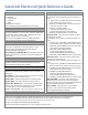

Schematic Symbol Naming Convention
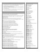
Default Family Codes
The first character is either "H" or "V" for horizontal or vertical wire insertion.
The next two characters are reserved for family type (for example, PB for
push buttons, CR for control relays, LS for limit switches).
The fourth character is generally a 2 for child contacts and 1 for everything
else (parent or standalone component).
If the symbol is a contact, then the fifth character is a 1 for normally open, 2
for normally closed.
The remaining characters are not specified. They are used to keep names
unique. Symbol names are limited to 32 characters.
AM: Ammeters
AN: Buzzers, horns, bells
CB: Circuit breakers
C0: Connectors/pins
CR: Control relays
DI: Din Rail
DN: Device networks
DO: Diodes
DR: Drives
DS: Disconnect switches
EN: Enclosures/hardware
FM: Frequency meters
FS: Flow sensors
FT: Foot switches
FU: Fuses
LR: Latching relays
LS: Limit switches
LT: Lights, pilot lights
MISC: Miscellaneous
MO: Motors
MS: Motor starters/contactors
NP: Nameplates
OL: Overloads
PB: Push buttons
PE: Photo switches
PLCIO: Programmable logic controllers
PM: Power meters
PNEU-ACT: Actuators
PNEU-ALU: Lubricators
PNEU-CYL: Cylinders
PNEU-FLC: Flow Control
PNEU-FLT: Filters
PNEU-MET: Pressure Gauges
PNEU-MFL: Silencers
PNEU-MNF: Manifolds
PNEU-MOT: Motors
PNEU-NOZ: Nozzles
PNEU-OPR: Push buttons
PNEU-PMP: Pumps
PNEU-TNK: Reservoirs
PNEU-VAC: Suction
PNEU-VLV: Valves
PS: Pressure switches
PW: Power supplies
PX: Proximity switches
RE: Resistors
SS: Selector switches
SU: Surge suppressors
SW: Toggle switches
TD: Timer relays
TRMS: Terminal blocks
TS: Temperature switches
VM: Volt meters
WO: Cables, multi-conductor cables
WW: Wire ways
XF: Transformers
Replaceable Parameters
Replaceable parameters are codes used to define tagging formats.
Device tags, wire numbers, cross-reference parameters:
%F: Component family code string (for example, "PB," "SS," "CR," "FLT," "MTR")
%S: Sheet number of the drawing (for example, "01" entered in upper right)
%D: Drawing number
%G: Wire layer name
%N: Sequential or Reference-based number applied to the component
%X: Suffix character position for reference-based tagging (not present = end of
tag)
%P: IEC-style project code (default for drawing)
%I: IEC-style installation code (default for drawing)
%L: IEC-style location code (default for drawing)
%A: Project drawing list's SEC value for active drawing
%B: Project drawing list's SUB-SEC value for active drawing
Wire annotation and graphical terminal strips parameters:
%P: Terminal pin text
%Q: Terminal pin TERMDESC text
%I: IEC-style installation code
%L: IEC-style location code
%M: Mount assignment (on panel footprint equivalent)
%U: Group assignment (on panel footprint equivalent)
%W: Wire number
%C: Cable tag + conductor/core color combination (format is "tag-color")
%E: Cable tag
%J: Cable conductor/core color
%V: Cable tag substituted for wire number if cable tag is non-blank.The wire
number is displayed when a cable ID does not exist.
%G: Wire color/gauge (or wire layer name)
%H: Cable wire color substituted for wire number if cable color is non-blank.The
wire layer is displayed when a wire conductor in conjunction with a cable ID does
not exist.
%T: Terminal strip terminal pin assignment
%K: Terminal strip TERMDESC text - useful for multi-stack terminals
%1: Destination component tag ID.
%2: Equivalent of "%1:%P" (comp tag:term)
%3: Equivalent of "%1:%P:%D" (comp tag:term:termdesc)
%4: Equivalent of "%L%1" (IEC comp tag)
%5: Equivalent of "%L%1:%P" (tag:term)
%6: Equivalent of "%L%1:%P:%D" (tag:term:termdesc)
%7: Equivalent of "%I%I%1" (INST prefix+IEC comp tag)
%8: Equivalent of "%I%L%1:%P" (tag:term)
%9: Equivalent of "%I%L%1:%P:%D" (tag:term:termdesc)
Note: You can use only one of the (%number) parameters.