
User Guide

AUTOCAD 2010 PREVIEW GUIDE
www.autodesk.com/autocad http://heidihewett.blogs.com/ 13
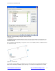
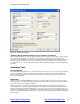
bar, apply transparency, and automatically show the constraint bars after applying constraints to selected
objects regardless of the current constraint bar visibility setting.
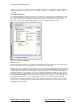
Figure 21. Constraint Settings dialog box, Geometric tab
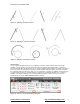
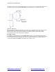
Establishing Dimensional Relationships
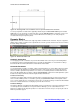
Dimensional relationships put limits on measurements of geometry. For example, you could use a dimensional
constraint to specify the radius of an arc, the length of a line, or that two parallel lines are always 15 mm apart.
Changing the value of a dimensional constraint forces a change in geometry.
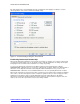
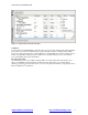
You can create dimensional constraints from the Dimensional panel of the Parametric tab or with the
DIMCONSTRAINT command. There are seven types of dimensional constraints, similar to the different kinds of
dimensions: Linear, Aligned, Horizontal, Vertical, Angular, Radial, and Diameter. In fact, you can use the
DIMCONSTRAINT command to convert a traditional dimension to the corresponding dimensional constraint.
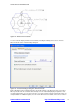
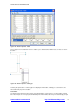
Dimensional constraints are assigned a name when created. The text of a dimensional constraint can display its
name, value, or its name and expression (name = formula or equation or value). A “lock” icon appears next to
all dimensional constraints to help you visually distinguish them from regular dimensions. By default,
dimensional constraints are displayed with a fixed system style that is zoom-invariant—it stays the same size
relative to the screen when you zoom in and out so it is always readable.