AutoCAD® 2010 Preview Guide www.autodesk.
AUTOCAD 2010 PREVIEW GUIDE Table of Contents Introduction ........................................................................................................................................................ 3 User Interface ..................................................................................................................................................... 3 Initial Setup .....................................................................................................................
AUTOCAD 2010 PREVIEW GUIDE Introduction With AutoCAD® 2010 software, you can tackle your most challenging problems with ease. Your designs can now exist in any shape imaginable, thanks to free-form design tools. Many critical features have been automated, making your workflow more efficient and the move to 3D design even smoother. Sharing and working on projects with colleagues has never been easier, thanks to multiple upgrades to our PDF capabilities and the incredible addition of 3D printing.
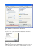
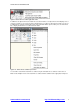
AUTOCAD 2010 PREVIEW GUIDE Figure 2. Initial Setup on User Preferences tab of the Options dialog box Workspaces When you specify Initial Setup options, AutoCAD automatically creates a new workspace based on your choices and sets it current. The name of the current workspace is displayed in the status bar next to the Workspace Switching icon and you can select it to access the Workspace menu. Figure 3.
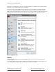
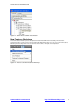
AUTOCAD 2010 PREVIEW GUIDE drawing as an email attachment, and produce electronic transmittal sets. In addition, you can perform drawing maintenance, such as audit and purge, and close drawings. A search tool at the top of the Application menu enables you to query the Quick Access toolbar, Application menu, and the currently loaded ribbon to locate commands, ribbon panel names, and other ribbon controls.
AUTOCAD 2010 PREVIEW GUIDE Figure 5. Ribbon and sticky panels The vertical ribbon, which can be displayed by undocking the ribbon from its horizontal position, has been updated to show the tab names along the side. The panel titles are displayed by default and those with additional tools include slide-out panels. When resizing the vertical ribbon, buttons automatically flow to the next or previous row and other elements, such as slider bars, automatically shorten or lengthen. Figure 6.
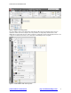
AUTOCAD 2010 PREVIEW GUIDE If you customized the Dashboard in AutoCAD 2008, you can easily convert your custom dashboard panels to new ribbon panels using the Transfer tab in the Customize User Interface (CUI) Editor. The newly converted panels are then displayed under the Ribbon Panels node in the same CUIx file as the dashboard panels. Once converted, you can add the new panels to a tab or transfer them to another CUIx file. Figure 7.
AUTOCAD 2010 PREVIEW GUIDE Figure 9. Quick Access toolbar right-click menu In addition to the right-click menu, the Quick Access toolbar includes a new flyout menu, which displays a list of common tools that you can select to include in the Quick Access toolbar. The flyout menu provides easy access to additional tools using the Command List pane in the CUI Editor. Other options enable you to show the menu bar or display the Quick Access toolbar below the ribbon. Figure 10.
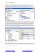
AUTOCAD 2010 PREVIEW GUIDE Figure 11. Quick Access toolbar customization New Features Workshop The New Features Workshop has been updated to include AutoCAD 2010 functionality. This interactive learning tool helps you discover the newest functionality with minimal effort. You can access the New Features Workshop from the drop-down menu on the InfoCenter toolbar, to the right of the Help button. Figure 12. Access to the New Features Workshop www.autodesk.com/autocad http://heidihewett.blogs.
AUTOCAD 2010 PREVIEW GUIDE Document AutoCAD is synonymous with documentation for good reason. Drive your projects from concept to completion with the powerful documentation tools in AutoCAD 2010. Work faster with automation, management, and editing tools that minimize repetitive tasks and speed your time to completion. No matter your project’s size or scope, you can meet the challenge with AutoCAD—continuously leading and innovating documentation for over 25 years.
AUTOCAD 2010 PREVIEW GUIDE Figure 15. Applying a parallel constraint Figure 16. Applying a coincident constraint Figure 17. Applying a concentric constraint AutoConstrain You can significantly automate the process of applying constraints using the AutoConstrain functionality, available on the Geometric panel of the Parametric tab. AutoConstrain automatically applies constraints to geometry that falls within specified tolerances.
AUTOCAD 2010 PREVIEW GUIDE Figure 19. Constraint Settings dialog box, AutoConstrain tab Constraint Bars Constraint bars show the constraints applied to an object. You can control the display of constraint bars using the CONSTRAINTBAR command or the Show, Show All, and Hide All options on the Geometric panel of the Parametric ribbon tab. When constraint bars are displayed, you can pass the cursor over a constraint to view the constraint name and the objects that it affects. Figure 20.
AUTOCAD 2010 PREVIEW GUIDE bar, apply transparency, and automatically show the constraint bars after applying constraints to selected objects regardless of the current constraint bar visibility setting. Figure 21. Constraint Settings dialog box, Geometric tab Establishing Dimensional Relationships Dimensional relationships put limits on measurements of geometry.
AUTOCAD 2010 PREVIEW GUIDE Figure 22. Dimensional constraints You can control the display of dimensional constraints, including the visibility of the lock icon, from the Dimensional tab of the Constraint Settings dialog box. Figure 23. Constraint Settings dialog box, Dimensional tab Easily edit a dimensional constraint using grips or by double-clicking on the dimension text to enter values.
AUTOCAD 2010 PREVIEW GUIDE formulas to set the values of other constraints. For example, if you have a rectangle with constraints named “length” and “width,” you could define the value of “width” as “length/3” to constrain the rectangle’s width to 1/3 of its length. User-Defined Parameters The Parameters Manager, available from the ribbon, enables you to manage dimensional parameters as well as create and manage user-defined parameters.
AUTOCAD 2010 PREVIEW GUIDE Figure 25: Rectangle with one annotational and one dynamic dimensional constraint You can specify which constraint form is applied by default using the CCONSTRAINTFORM system variable. Additionally, you can specify the constraint form when using the DIMCONSTRAINT command to create a new dimensional constraint. Even after you have created a dimensional constraint, you can easily change its constraint form using the Properties palette.
AUTOCAD 2010 PREVIEW GUIDE Figure 27. Block Editor Parameters Manager Test Blocks A new Test Block tool (BTESTBLOCK command) enables you to test a block definition while authoring dynamic blocks. When you use this tool, AutoCAD opens a temporary window, similar to a drawing window, with the block reference already inserted. The Test Block Window is easily identifiable by the title bar, background color, and the contextual ribbon tab which includes a button to Close Test Block.
AUTOCAD 2010 PREVIEW GUIDE Figure 28. Block Properties Table A menu grip on the inserted block reference enables you to switch between different sets of values or rows in the table. Figure 29. Block Properties Table grip Selecting “Properties table..” from the grip menu displays the Block table, enabling you set the block to the values defined by any row in the table. Action Bars The display and positioning of Action objects in the Block Editor is enhanced to be consistent with Constraint bars.
AUTOCAD 2010 PREVIEW GUIDE into Action bars based on the parameters with which they are associated. You can toggle between the new and old display styles by setting the BACTIONBARMODE system variable prior to entering the Block Editor. Figure 30. Action bars When viewing the block definition with Action bars turned on, you can quickly tell which actions are associated with which parameters and how many actions each of the parameters affects.
AUTOCAD 2010 PREVIEW GUIDE Figure 31. Block Editor Settings Authoring Blocks with Constraints versus Parameters and Actions When creating dynamic blocks using geometric and dimensional constraints, it is generally recommended that you don’t mix them with parameters and actions. For example, if you apply geometric constraints to the geometry in the block definition, you should use constraint parameters to define custom properties for the block instead of the action parameters.
AUTOCAD 2010 PREVIEW GUIDE The MLEADEREDIT command has been streamlined by eliminating the need for you to select an option to add or remove leader lines. It adds leaders by default until you select the option to remove leaders. Mtext Mtext improvements include a default column mode of Dynamic with manual height. In addition, the corner grips on mtext objects are now consistent with the corner grips on table objects.
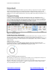
AUTOCAD 2010 PREVIEW GUIDE Hatch When a hatch boundary area is not found, AutoCAD attempts to show you where the problem may have occurred. Red circles appear around endpoints near where any gap in geometry is estimated to be. Figure 33. Hatch boundary gap Additional enhancements provide more robust boundary detection and the ability to edit nonassociative hatch objects. You can select on a non-associative hatch and then use intuitive grips to dynamically change its shape. Figure 34.
AUTOCAD 2010 PREVIEW GUIDE Measure Tools The new MEASUREGEOM command enables you to measure the distance, radius, angle, area, or volume of a selected object or a sequence of points. You can access these tools from the Utilities panel of the Home ribbon tab. The default option is Distance. However, selecting a different measure tool will set it as the default for the remainder of the AutoCAD session or until a different tool is selected. Figure 36.
AUTOCAD 2010 PREVIEW GUIDE You can use the Volume tool to specify boundary points with visual feedback similar to the Area option, and then specify a height to determine the volume. Additionally, you can display the volume of selected solids or regions. Figure 38. Volume highlighting Reverse Tools The new REVERSE command enables you to reverse the direction of lines, polylines, splines, and helixes. Simply select the object(s) to reverse.
AUTOCAD 2010 PREVIEW GUIDE Figure 40. Reverse option Spline Editing Tools The updated SPLINEDIT command includes a new option to convert a spline to a polyline. You can launch the SPLINEDIT command from the Modify ribbon panel. Select the spline you want to edit and choose the Convert to Polyline option. You’ll then be prompted to specify a precision for the conversion. Enter any value between 0 and 99. The higher the value, the more accurate the polyline. Figure 41. Convert to Polyline option www.
AUTOCAD 2010 PREVIEW GUIDE In addition to the new Convert to Polyline option in the SPLINEDIT command, you can use the updated PEDIT command to select a Spline object and automatically convert it to a polyline. After selecting the spline and confirming that “Yes” you really do want to convert it, you can specify the precision between 0 and 99. Figure 42.
AUTOCAD 2010 PREVIEW GUIDE Figure 44. Options dialog box Purge Tools The Purge dialog box has been updated to include an option for purging zero-length geometry and empty text objects. Figure 45. Purge dialog box www.autodesk.com/autocad http://heidihewett.blogs.
AUTOCAD 2010 PREVIEW GUIDE How do you create zero-length geometry or empty text objects? Usually by accident! For example, you might grip-edit a line and accidentally snap one endpoint onto the other endpoint. Or you might begin creating an mtext, enter a space, and then cancel out of it. The mtext object still exists but you can’t see it because it is nothing more than a space. After performing the Purge operation, AutoCAD will report how many zero-length or empty text objects it purged.
AUTOCAD 2010 PREVIEW GUIDE When you select a reference file in the drawing, a relevant contextual tab is automatically displayed in the ribbon. For example, if you select a PDF underlay, the PDF Underlay tab is displayed providing you easy access to PDF underlay tools. Figure 48. PDF Underlay contextual tab Easily edit the clip boundary of any reference using grips. You can even invert the clip with a simple click on the invert grip! Figure 49.
AUTOCAD 2010 PREVIEW GUIDE Figure 51. Underlay controls When you open a drawing that has unresolved references, a new tool helps identify the missing files. Figure 52. Unresolved Reference Files If you choose Update, AutoCAD opens the External References palette so you can repath the missing files. If you choose Ignore, the warning closes and takes no action. If you always want to ignore unresolved references, use the checkbox at the bottom to stop the warning from displaying again.
AUTOCAD 2010 PREVIEW GUIDE Sheet List Table functionality is more flexible than ever before. In addition to creating a sheet list table for the entire sheet set, you can now insert a sheet list table for individual subsets and even individual sheets. You can access this functionality from the right-click menu in the Sheet List table and a new tab in the Sheet List Table dialog box enables you to control the behavior of subsets and sheets.
AUTOCAD 2010 PREVIEW GUIDE You can use the Plotter Configuration Editor to view and modify the PDF settings for plotted output. Select the DWG to PDF.pc3 plotter in the Plot dialog box and then choose Properties. The new Merge Control option is displayed under the Graphics node and the other options are accessible when you select Custom Properties. Figure 54.
AUTOCAD 2010 PREVIEW GUIDE Figure 56. Sheet Set and Publish Options PDF Underlays AutoCAD 2010 addresses one of the top AUGI® (Autodesk User Group International) wish list requests by enabling you to attach a PDF file to an AutoCAD drawing as an underlay. You can work with PDF underlays in the same way you work with other external references including DWG, DWF, DGN, and Image files. You can even snap to key points on PDF geometry using familiar object snaps.
AUTOCAD 2010 PREVIEW GUIDE Figure 57.Auto-complete Object Size Limits In previous versions of AutoCAD, no single object in an AutoCAD drawing could be larger than 256 MB. In AutoCAD 2010, the object size limit has been increased to at least 4 GB (depending on your system configuration), providing more flexibility. These large objects, however, are not backwards-compatible, so a new compatibility option has been added to the Open and Save tab of the Options dialog box. Figure 58.
AUTOCAD 2010 PREVIEW GUIDE preparing your model, adjusting the scale, creating an STL file from your model, then downloading your STL file to a user-specified vendor for printing. The final 3D model will be printed then shipped to you within days. You can prepare your model for 3D printing using the 3DPRINT command or selecting Send to 3D Print Service from the output tab. Select all solid objects you want to print.
AUTOCAD 2010 PREVIEW GUIDE Figure 60. Seek search results AutoCAD 2010 will also enable vendors to easily upload their designs to Seek using the Share with Autodesk Seek utility. This utility enables product vendors to move their product to the market quicker than ever before, so that AutoCAD designers can specify actual products in their designs. Figure 61.
AUTOCAD 2010 PREVIEW GUIDE Figure 62. Share with Autodesk Seek dialog box Explore AutoCAD 2010 gives you 3D power to explore your ideas in almost any shape imaginable. AutoCAD and a blank canvas have a lot in common. Both give you the ability to create the previously unimaginable. But AutoCAD provides the flexibility to explore design ideas in both 2D and 3D, with intuitive tools that help your concepts become real.
AUTOCAD 2010 PREVIEW GUIDE Figure 64. Variations of a conceptual design AutoCAD 2010 includes a new 3D Scale gizmo in addition to the 3D Move and 3D Rotate gizmos. Using these gizmos, you can move, rotate, or scale selected objects within the constraints of a specified axis or plane. Figure 65.
AUTOCAD 2010 PREVIEW GUIDE Figure 67. Move gizmo with planar constraint A new context menu, available when you right-click on a gizmo axis or plane, enables you to change the gizmo’s behavior. You can set the constraint to a different axis or plane, switch between the 3D Move, 3D Rotate, and 3D Scale gizmos, relocate the gizmo, and align it to the world UCS, current UCS, or an object face.
AUTOCAD 2010 PREVIEW GUIDE Figure 70. Subobject selection filters With the subobject selection filter set to vertex, for example, you can ensure that when you press CTRL and pick on the corner of an object, AutoCAD will select the vertex rather than the edge. Figure 71. Subobject editing The Solid Editing panel of the Home tab includes tools to perform unions, subtractions, interferences, intersections, and imprinting.
AUTOCAD 2010 PREVIEW GUIDE Figure 72. Example of free-form shapes The new Mesh Modeling ribbon tab provides easy access to the mesh creation and editing tools. The Primitives panel includes a tool to create primitive mesh shapes (Box, Cone, Cylinder, Pyramid, Sphere, Wedge, and Torus) as well as revolved, ruled, tabbed, and edge mesh surfaces. Figure 73. Mesh Modeling ribbon tab A mesh object can be incrementally smoothed to create curved shapes, even when starting with a traditional primitive shape.
AUTOCAD 2010 PREVIEW GUIDE can crease subobjects near existing buildings and at the base to ensure they remain unaffected by the mesh smoothness. Combining the crease, smoothness, and refine functionality enables you to create smooth shapes within a hard-edged scenario. Figure 75. Mesh Crease Unlike their solid equivalents, the faces of mesh objects are divided into smaller faces based on mesh tessellation values.
AUTOCAD 2010 PREVIEW GUIDE Figure 77. Mesh Tessellation Options Mesh editing tools, available in the Mesh Edit panel of the ribbon, enable you to edit mesh faces as well as convert between surfaces and solids. You can split a mesh face by specifying two split points. You can then select and edit each new face, as well as the edges and vertices that they produce, using the CTRL key for subobject selection. Selecting individual subobjects enables you to further modify the shape of the mesh.
AUTOCAD 2010 PREVIEW GUIDE Figure 79. Extruded face After using the mesh creating and editing tools to create organic meshes, you can convert those that are watertight (no gaps) and not self-intersecting, to smooth or faceted solids. Additional tools enable you to convert meshes to smooth or faceted surfaces and you can control the smoothness of objects during the conversion process. These conversion tools are available in the Convert Mesh panel of the ribbon tab. Figure 80.
AUTOCAD 2010 PREVIEW GUIDE when using dynamic input. In addition, the playback user messages have been streamlined for increased clarity. A new command enables you to establish base points at specified locations in your action macro. You can access the new ACTBASEPOINT command as a button in the Action Recorder panel or as a right-click menu option in the Action Tree. Figure 81.
AUTOCAD 2010 PREVIEW GUIDE Figure 82. Action Macro Manager Online License Transfer AutoCAD 2010 includes a new Online License Transfer (OLT) Utility that enables you to move stand-alone licenses between computers. It replaces the Portable License Utility (PLU) used in previous Autodesk product releases. You can access OLT functionality from the AutoCAD 2010>License Transfer Utility option in the Start menu. Figure 83.
AUTOCAD 2010 PREVIEW GUIDE Summary With AutoCAD 2010, you can tackle your most challenging problems with ease. Create almost any shape imaginable with free-from design tools, cut revision time and keep everything connected with parametric drawing, share your ideas as PDFs, or bring them to life with 3D printing. AutoCAD 2010 takes you from idea to reality faster. Autodesk, AutoCAD, AUGI, DWF, and DWG are registered trademarks or trademarks of Autodesk, Inc.