
User`s guide
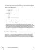
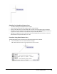
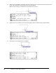
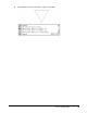
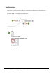
Table Of Contents
- Introduction
- Chapter 1: Taking the AutoCAD Tour
- Chapter 2: Creating Basic Drawings
- Chapter 3: Manipulating Objects
- Lesson: Selecting Objects in the Drawing
- Lesson: Changing an Object's Position
- Lesson: Creating New Objects from Existing Objects
- Lesson: Changing the Angle of an Object's Position
- Lesson: Creating a Mirror Image of Existing Objects
- Lesson: Creating Object Patterns
- Lesson: Changing an Object's Size
- Challenge Exercise: Grips
- Challenge Exercise: Architectural
- Challenge Exercise: Mechanical
- Chapter Summary
- Chapter 4: Drawing Organization and Inquiry Commands
- Chapter 5: Altering Objects
- Lesson: Trimming and Extending Objects to Defined Boundaries
- Lesson: Creating Parallel and Offset Geometry
- Lesson: Joining Objects
- Lesson: Breaking an Object into Two Objects
- Lesson: Applying a Radius Corner to Two Objects
- Lesson: Creating an Angled Corner Between Two Objects
- Lesson: Changing Part of an Object's Shape
- Challenge Exercise: Architectural
- Challenge Exercise: Mechanical
- Chapter Summary

Lesson: Inputting Data ■ 59
Guidelines for Using Direct Distance Entry
■ Turn Polar Tracking on to display the cursor's angle.
■ Set the desired incremental polar angles in Polar Tracking settings.
■ Enter the desired distance and press ENTER. Be sure that the accurate Polar angle is displayed.
■ AutoCAD is accurate 14 places to the right of the decimal point (1.00000000000000). Therefore, it
is important to enter the distance and use Polar Snap for absolute precision.
■ Although turning Dynamic Input off limits the data fields displayed by your pointer, you may use
Direct Distance entry with this feature on or off.
Procedure: Using Direct Distance Entry
The following steps give an overview for using the direct distance entry method.
1.
Start a command such as Line and click a point to begin.
Tip: Toggle off Dynamic Input on the status bar for clearer results.