
User`s guide
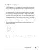
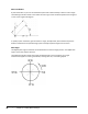
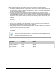
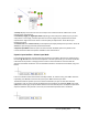
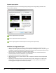
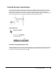
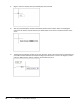
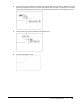
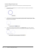
Table Of Contents
- Introduction
- Chapter 1: Taking the AutoCAD Tour
- Chapter 2: Creating Basic Drawings
- Chapter 3: Manipulating Objects
- Lesson: Selecting Objects in the Drawing
- Lesson: Changing an Object's Position
- Lesson: Creating New Objects from Existing Objects
- Lesson: Changing the Angle of an Object's Position
- Lesson: Creating a Mirror Image of Existing Objects
- Lesson: Creating Object Patterns
- Lesson: Changing an Object's Size
- Challenge Exercise: Grips
- Challenge Exercise: Architectural
- Challenge Exercise: Mechanical
- Chapter Summary
- Chapter 4: Drawing Organization and Inquiry Commands
- Chapter 5: Altering Objects
- Lesson: Trimming and Extending Objects to Defined Boundaries
- Lesson: Creating Parallel and Offset Geometry
- Lesson: Joining Objects
- Lesson: Breaking an Object into Two Objects
- Lesson: Applying a Radius Corner to Two Objects
- Lesson: Creating an Angled Corner Between Two Objects
- Lesson: Changing Part of an Object's Shape
- Challenge Exercise: Architectural
- Challenge Exercise: Mechanical
- Chapter Summary

Lesson: Inputting Data ■ 53
Using the Dynamic Input Interface
You can usethe Dynamic Input interface in several ways, buttheprimary goal of the tool is to let you
draw and edit in a heads-up mode, with your focus on the graphics window instead of the command
line. Because the Dynamic Input interface is context sensitive, its options and display modes are
dependent on the context in which you are working. The following guidelines give an overview of how
you can use the Dynamic Input interface during typical drawing and editing tasks.
Command Access
Dynamic Input Mode
Command Line: DYNMODE
Function Key: F12
Procedure: Drawing with Dynamic Input
The following steps give an overview of creating geometry using the Dynamic Input interface and Polar
coordinates. Note that because the Dynamic Input display is activated, relativity is assumed and it is
not necessary to enter the ampersand symbol (@).