
User`s guide
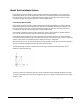
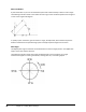
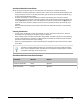
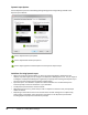
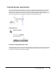
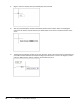
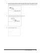
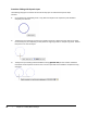
Table Of Contents
- Introduction
- Chapter 1: Taking the AutoCAD Tour
- Chapter 2: Creating Basic Drawings
- Chapter 3: Manipulating Objects
- Lesson: Selecting Objects in the Drawing
- Lesson: Changing an Object's Position
- Lesson: Creating New Objects from Existing Objects
- Lesson: Changing the Angle of an Object's Position
- Lesson: Creating a Mirror Image of Existing Objects
- Lesson: Creating Object Patterns
- Lesson: Changing an Object's Size
- Challenge Exercise: Grips
- Challenge Exercise: Architectural
- Challenge Exercise: Mechanical
- Chapter Summary
- Chapter 4: Drawing Organization and Inquiry Commands
- Chapter 5: Altering Objects
- Lesson: Trimming and Extending Objects to Defined Boundaries
- Lesson: Creating Parallel and Offset Geometry
- Lesson: Joining Objects
- Lesson: Breaking an Object into Two Objects
- Lesson: Applying a Radius Corner to Two Objects
- Lesson: Creating an Angled Corner Between Two Objects
- Lesson: Changing Part of an Object's Shape
- Challenge Exercise: Architectural
- Challenge Exercise: Mechanical
- Chapter Summary

Lesson: Inputting Data ■ 49
Absolute and Relative Coordinates
When you type coordinates, they can be in the form of an absolute or a relative coordinate.
■ An absolute coordinate represents a specific point in the current coordinate system relative to the
origin point (0,0). To enter an absolute coordinate, type the values as a Cartesian coordinate (x,y)
or Polar coordinate (distance angle).
■ A relative coordinate is a point located from a previously selected point. To enter a relative
coordinate, select your first point, then precede the next coordinate point with the @ symbol. For
example @5<45 would mean 5 units at 45 degrees from the last point selected, and @3,5 would
mean 3 units in the positive x direction and 5 units in the positive y direction from the last point
selected.
Note that when the Dynamic Input option is selected in the Status Bar relativity is automatically
assumed.
Entering Coordinates
■ You can enter coordinates any time the software is in point acquisition mode, that is, when the
Command line is prompting you to specify a point or distance.
■ Every drawing contains the world coordinate system (WCS). The WCS is identical in every drawing
and cannot be altered. For example, an object placed at the absolute coordinate 10,10 would be
positioned in the same location in any drawing.
■ Unless you specifically define a User Coordinate System, all geometry you create is drawn relative
to the WCS.
The UCS icon displays differently when you are working in the world coordinate system
versus a user coordinate system. The UCS icon for the world coordinate system contains
a small box at the origin of the X and Y axes.
Absolute and Relative Coordinate Examples
Coordinate
Absolute
Relative
Cartesian coordinate
24,46
@24,46
Polar coordinate
15<45
@15<45