
User`s guide
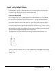
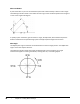
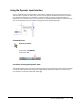
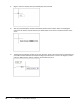
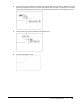
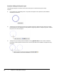
Table Of Contents
- Introduction
- Chapter 1: Taking the AutoCAD Tour
- Chapter 2: Creating Basic Drawings
- Chapter 3: Manipulating Objects
- Lesson: Selecting Objects in the Drawing
- Lesson: Changing an Object's Position
- Lesson: Creating New Objects from Existing Objects
- Lesson: Changing the Angle of an Object's Position
- Lesson: Creating a Mirror Image of Existing Objects
- Lesson: Creating Object Patterns
- Lesson: Changing an Object's Size
- Challenge Exercise: Grips
- Challenge Exercise: Architectural
- Challenge Exercise: Mechanical
- Chapter Summary
- Chapter 4: Drawing Organization and Inquiry Commands
- Chapter 5: Altering Objects
- Lesson: Trimming and Extending Objects to Defined Boundaries
- Lesson: Creating Parallel and Offset Geometry
- Lesson: Joining Objects
- Lesson: Breaking an Object into Two Objects
- Lesson: Applying a Radius Corner to Two Objects
- Lesson: Creating an Angled Corner Between Two Objects
- Lesson: Changing Part of an Object's Shape
- Challenge Exercise: Architectural
- Challenge Exercise: Mechanical
- Chapter Summary

48 ■ Chapter 2: Creating Basic Drawings
Polar Coordinates
A polar coordinate is a point in the coordinate system that is determined by a distance and an angle.
The following illustration shows a line drawn from the origin of the coordinate system with a length of
7 units and an angle of 45 degrees.
To specify a polar coordinate, type the distance < angle, example 5<45, where Distance equals the
distance traveled from the specified origin point and Angle equals the angle from the X axis.
Polar Angle
The default polar angle is measured counterclockwise from the zero angle position. The default zero
angle is in the East compass direction.
The following illustration shows how angles are defined with a polar coordinate. This angle
measurement applies to entering coordinates, working with arcs, and rotating objects.