
User`s guide

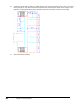
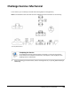
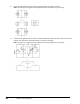
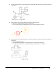
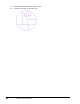

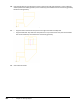

Table Of Contents
- Introduction
- Chapter 1: Taking the AutoCAD Tour
- Chapter 2: Creating Basic Drawings
- Chapter 3: Manipulating Objects
- Lesson: Selecting Objects in the Drawing
- Lesson: Changing an Object's Position
- Lesson: Creating New Objects from Existing Objects
- Lesson: Changing the Angle of an Object's Position
- Lesson: Creating a Mirror Image of Existing Objects
- Lesson: Creating Object Patterns
- Lesson: Changing an Object's Size
- Challenge Exercise: Grips
- Challenge Exercise: Architectural
- Challenge Exercise: Mechanical
- Chapter Summary
- Chapter 4: Drawing Organization and Inquiry Commands
- Chapter 5: Altering Objects
- Lesson: Trimming and Extending Objects to Defined Boundaries
- Lesson: Creating Parallel and Offset Geometry
- Lesson: Joining Objects
- Lesson: Breaking an Object into Two Objects
- Lesson: Applying a Radius Corner to Two Objects
- Lesson: Creating an Angled Corner Between Two Objects
- Lesson: Changing Part of an Object's Shape
- Challenge Exercise: Architectural
- Challenge Exercise: Mechanical
- Chapter Summary

Challenge Exercise: Mechanical ■ 441
4.
Create and edit geometry so the side view for the Rack Slider Base appears as shown. Note the 3mm
radius fillets.
5.
Copy geometry from the area indicated to the upper-right of the view.
■ Scale the resulting geometry to twice its regular size.
■ Draw a circle around the scaled geometry, then trim the geometry to the circle.
6.
Copy geometry from the existing views to create the assembly views. You won't need the hidden and
centerlines.
■ Thaw the Start Points layer.
■ Use the Assembly Start Point to locate the position of the assembly front view.
■ Erase geometry as required if it would be hidden by other parts as it is assembled.