
User`s guide
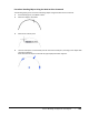

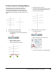
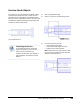


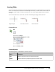
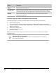
Table Of Contents
- Introduction
- Chapter 1: Taking the AutoCAD Tour
- Chapter 2: Creating Basic Drawings
- Chapter 3: Manipulating Objects
- Lesson: Selecting Objects in the Drawing
- Lesson: Changing an Object's Position
- Lesson: Creating New Objects from Existing Objects
- Lesson: Changing the Angle of an Object's Position
- Lesson: Creating a Mirror Image of Existing Objects
- Lesson: Creating Object Patterns
- Lesson: Changing an Object's Size
- Challenge Exercise: Grips
- Challenge Exercise: Architectural
- Challenge Exercise: Mechanical
- Chapter Summary
- Chapter 4: Drawing Organization and Inquiry Commands
- Chapter 5: Altering Objects
- Lesson: Trimming and Extending Objects to Defined Boundaries
- Lesson: Creating Parallel and Offset Geometry
- Lesson: Joining Objects
- Lesson: Breaking an Object into Two Objects
- Lesson: Applying a Radius Corner to Two Objects
- Lesson: Creating an Angled Corner Between Two Objects
- Lesson: Changing Part of an Object's Shape
- Challenge Exercise: Architectural
- Challenge Exercise: Mechanical
- Chapter Summary

398 ■ Chapter 5: Altering Objects
Guidelines for Breaking Objects
■ You can use the Break command on lines, circles, arcs, polylines, and splines.
■ If you do not manually specify the first point, the point at which the object was selected is used as
the first point.
■ When breaking an object at the intersection of another object, be sure to specify which object you
want to break first.
■ Circles break in a counter-clockwise direction. The portion that gets removed depends on the
order in which you select the breakpoints.
■ You can use the @ key and press ENTER to use the first point as the second point, which results in
the object being broken in such a way that the resulting endpoints are coincident.
When to use Break
Use the Break command only when there are no cutting edges that would allow you to
use the Trim command or to break an object at a specific point without a gap.