
User`s guide
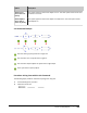
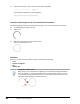
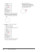

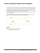
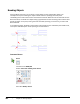
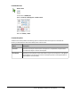

Table Of Contents
- Introduction
- Chapter 1: Taking the AutoCAD Tour
- Chapter 2: Creating Basic Drawings
- Chapter 3: Manipulating Objects
- Lesson: Selecting Objects in the Drawing
- Lesson: Changing an Object's Position
- Lesson: Creating New Objects from Existing Objects
- Lesson: Changing the Angle of an Object's Position
- Lesson: Creating a Mirror Image of Existing Objects
- Lesson: Creating Object Patterns
- Lesson: Changing an Object's Size
- Challenge Exercise: Grips
- Challenge Exercise: Architectural
- Challenge Exercise: Mechanical
- Chapter Summary
- Chapter 4: Drawing Organization and Inquiry Commands
- Chapter 5: Altering Objects
- Lesson: Trimming and Extending Objects to Defined Boundaries
- Lesson: Creating Parallel and Offset Geometry
- Lesson: Joining Objects
- Lesson: Breaking an Object into Two Objects
- Lesson: Applying a Radius Corner to Two Objects
- Lesson: Creating an Angled Corner Between Two Objects
- Lesson: Changing Part of an Object's Shape
- Challenge Exercise: Architectural
- Challenge Exercise: Mechanical
- Chapter Summary

Lesson: Breaking an Object into Two Objects ■ 395
Command Access
Break at Point
Command Line: BREAK, BR
Ribbon: Home tab > Modify panel > Break at Point
Menu Bar: Modify > Break
Command Options
The Break command provides the following options. Select the Break at Point option on the 2D Draw
panel if you want both first and second break points to be the same.
Option
Description
First Point
Specifies the first point of the break. If this option is not specified, the point where
you select the object is used as the first point.
Second Point
Specifies the second point of the break. Select any point on the object or enter @ and
press ENTER to use the first point as the second point (results in the object broken so
that endpoints are coincident).