
User`s guide
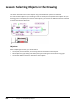
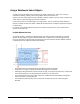
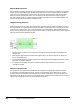
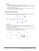
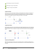
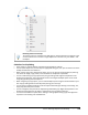
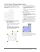
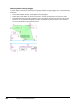
Table Of Contents
- Introduction
- Chapter 1: Taking the AutoCAD Tour
- Chapter 2: Creating Basic Drawings
- Chapter 3: Manipulating Objects
- Lesson: Selecting Objects in the Drawing
- Lesson: Changing an Object's Position
- Lesson: Creating New Objects from Existing Objects
- Lesson: Changing the Angle of an Object's Position
- Lesson: Creating a Mirror Image of Existing Objects
- Lesson: Creating Object Patterns
- Lesson: Changing an Object's Size
- Challenge Exercise: Grips
- Challenge Exercise: Architectural
- Challenge Exercise: Mechanical
- Chapter Summary
- Chapter 4: Drawing Organization and Inquiry Commands
- Chapter 5: Altering Objects
- Lesson: Trimming and Extending Objects to Defined Boundaries
- Lesson: Creating Parallel and Offset Geometry
- Lesson: Joining Objects
- Lesson: Breaking an Object into Two Objects
- Lesson: Applying a Radius Corner to Two Objects
- Lesson: Creating an Angled Corner Between Two Objects
- Lesson: Changing Part of an Object's Shape
- Challenge Exercise: Architectural
- Challenge Exercise: Mechanical
- Chapter Summary

160 ■ Chapter 3: Manipulating Objects
Manual Window Selection
You can define a selection window by using the Window selection method. In response to any Select
Objects prompt, enter W and press ENTER. This enables you to create a regular selection window in
which you are not restricted as to the direction of the cursor movement when defining the points.
When you specify the Window option, you can define the window from left-to-right or right-to-
left, and it always results in a regular selection window. Only objects that are completely within the
selection window will be included in the selection set.
Implied Crossing Selection
Implied crossing means that you have not manually specified a specific selection method. To make a
crossing selection, you specify opposite corners that define a rectangular area. The first corner point
must be in your drawing area, but cannot be touching any existing objects. After specifying the first
corner point, you drag the cursor from right to left to create a crossing selection that is in the opposite
direction of the previous Window selection.
■ All objects that are within or touched by the rectangular crossing window are included in the
selection set.
■ Although the drag movement must be from right to left, it can be up and across or down and
across the drawing area.
■ The crossing window has a dashed outline and a differently colored shading to distinguish it from
that used in a window selection.
■ The shaded area indicates the points in space that were used to define the corners of the
rectangular window.
Manual Crossing Selection
You can define a non-implied Crossing Window by using the Crossing Window selection method.
In response to any Select Objects prompt, enter C and press ENTER. This enables you to create a
Crossing selection window where the direction of the cursor movement is not restricted when you
define the points. When you specify Crossing Window, you can define the window from left to right or
right to left, and it always results in a Crossing selection window.