
User`s guide
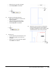
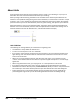
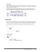
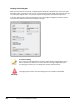
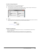
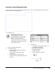
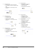
Table Of Contents
- Introduction
- Chapter 1: Taking the AutoCAD Tour
- Chapter 2: Creating Basic Drawings
- Chapter 3: Manipulating Objects
- Lesson: Selecting Objects in the Drawing
- Lesson: Changing an Object's Position
- Lesson: Creating New Objects from Existing Objects
- Lesson: Changing the Angle of an Object's Position
- Lesson: Creating a Mirror Image of Existing Objects
- Lesson: Creating Object Patterns
- Lesson: Changing an Object's Size
- Challenge Exercise: Grips
- Challenge Exercise: Architectural
- Challenge Exercise: Mechanical
- Chapter Summary
- Chapter 4: Drawing Organization and Inquiry Commands
- Chapter 5: Altering Objects
- Lesson: Trimming and Extending Objects to Defined Boundaries
- Lesson: Creating Parallel and Offset Geometry
- Lesson: Joining Objects
- Lesson: Breaking an Object into Two Objects
- Lesson: Applying a Radius Corner to Two Objects
- Lesson: Creating an Angled Corner Between Two Objects
- Lesson: Changing Part of an Object's Shape
- Challenge Exercise: Architectural
- Challenge Exercise: Mechanical
- Chapter Summary

Lesson: Working with Units ■ 143
Procedure: Setting Drawing Units
The following steps give an overview of setting drawing units.
1.
On the command line, enter units and press ENTER.
2.
In the Drawing Units dialog box, select the appropriate length and angle unit types. If necessary, you
can also adjust the precision options for both length and angle.
3.
Click OK.
4.
You can now enter values using the format of the selected unit for length and angle. When the software
presents values to you via the interface, they are in the selected unit format.
Guidelines for Setting Units
■ While it is possible to set the drawing units at any time, it is recommended that you do this when
you start a new drawing.
■ Regardless of the current unit setting, you can always enter units in decimal format.
■ To input values in a format other than decimal, you must set the appropriate unit type.