
User`s guide
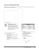
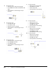
Table Of Contents
- Introduction
- Chapter 1: Taking the AutoCAD Tour
- Chapter 2: Creating Basic Drawings
- Chapter 3: Manipulating Objects
- Lesson: Selecting Objects in the Drawing
- Lesson: Changing an Object's Position
- Lesson: Creating New Objects from Existing Objects
- Lesson: Changing the Angle of an Object's Position
- Lesson: Creating a Mirror Image of Existing Objects
- Lesson: Creating Object Patterns
- Lesson: Changing an Object's Size
- Challenge Exercise: Grips
- Challenge Exercise: Architectural
- Challenge Exercise: Mechanical
- Chapter Summary
- Chapter 4: Drawing Organization and Inquiry Commands
- Chapter 5: Altering Objects
- Lesson: Trimming and Extending Objects to Defined Boundaries
- Lesson: Creating Parallel and Offset Geometry
- Lesson: Joining Objects
- Lesson: Breaking an Object into Two Objects
- Lesson: Applying a Radius Corner to Two Objects
- Lesson: Creating an Angled Corner Between Two Objects
- Lesson: Changing Part of an Object's Shape
- Challenge Exercise: Architectural
- Challenge Exercise: Mechanical
- Chapter Summary

140 ■ Chapter 2: Creating Basic Drawings
About Units
Units represent the baseline of all the geometry that you create in your drawing. It is up to you to
determine what unit of measurement will be used in your drawing.
When you begin a blank drawing, the default units are based in the decimal system. Because the
software is not capable of distinguishing inches from millimeters, it assumes that a value of 1 is equal
to either 1 inch or 1 mm. Setting the appropriate units determines the format in which the software
presents values to you via the command line, status bar, polar tracking, and dynamic input interface.
While the software is not a true units-based system, meaning it doesn't understand the difference
between 1 inch and 1 millimeter, there are some assumptions that can affect other settings such as
Imperial Architectural units (for example1'-6"), and alternate dimension display.
Unit Guidelines
The following are some guidelines you should refer to regarding units:
■ The software is set by default to decimal units.
■ A unit of 1 can be equal to 1 inch or 1 millimeter.
■ If you need to input imperial architectural units for distances, you must select the Architectural
type drawing units. The software will not understand the architectural units format 1'-6" if the
Units are set to Decimal.
■ When you are using Architectural Units, type the 'foot' mark, but it is not necessary to type
"inches" as the software will assume inches if no symbol is typed. Example 16' -2" can be simply
typed: 16'2
■ When using Architectural units, you may type 16' -2" or the equivalent in inches: 194
■ If you work primarily with metric units, then you should use the default decimal unit setting.
■ AutoCAD is accurate 14 decimal places (1.00000000000000). What you see for units precision will
be rounded up to the nearest decimal place that you have determined in the Units dialog box.
■ Simply picking points in the drawing window will not guarantee that you have specified the
precise length or angle unless you use the drawing aids determined in the drafting settings.