
User`s guide
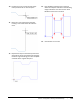
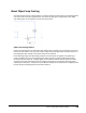
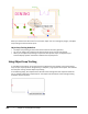

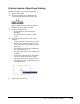
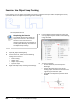
Table Of Contents
- Introduction
- Chapter 1: Taking the AutoCAD Tour
- Chapter 2: Creating Basic Drawings
- Chapter 3: Manipulating Objects
- Lesson: Selecting Objects in the Drawing
- Lesson: Changing an Object's Position
- Lesson: Creating New Objects from Existing Objects
- Lesson: Changing the Angle of an Object's Position
- Lesson: Creating a Mirror Image of Existing Objects
- Lesson: Creating Object Patterns
- Lesson: Changing an Object's Size
- Challenge Exercise: Grips
- Challenge Exercise: Architectural
- Challenge Exercise: Mechanical
- Chapter Summary
- Chapter 4: Drawing Organization and Inquiry Commands
- Chapter 5: Altering Objects
- Lesson: Trimming and Extending Objects to Defined Boundaries
- Lesson: Creating Parallel and Offset Geometry
- Lesson: Joining Objects
- Lesson: Breaking an Object into Two Objects
- Lesson: Applying a Radius Corner to Two Objects
- Lesson: Creating an Angled Corner Between Two Objects
- Lesson: Changing Part of an Object's Shape
- Challenge Exercise: Architectural
- Challenge Exercise: Mechanical
- Chapter Summary

Lesson: Using Object Snap Tracking ■ 129
About Object Snap Tracking
You often need to place or create geometry at a location relative to other objects in the drawing. While
you could create construction geometry for the purpose of aligning the new geometry, with object
snap tracking you can accomplish the same result much faster.
Object Snap Tracking Defined
Object snap tracking works in combination with object snaps to enable you to temporarily acquire and
track up to seven points. Once you acquire points, object snap tracking provides horizontal, vertical, or
polar alignment paths relative to the points that you have acquired.
In the following image, the table is being moved to the room center using object snap tracking. To
center the table in the room, the midpoint of the wall on the left (1) and the midpoint of the wall
below (2) have been acquired. Triangular glyphs at the midpoints indicate that the points have been
acquired. As the table is positioned near the imaginary intersection, the alignment paths (3) appear
indicating the intersection. The Dynamic Input interface displays the current position as 0 degrees from
the left midpoint and 90 degrees from the lower midpoint.