
User`s guide
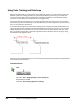
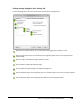
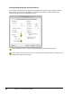
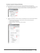
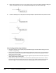
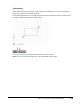
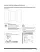
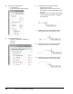
Table Of Contents
- Introduction
- Chapter 1: Taking the AutoCAD Tour
- Chapter 2: Creating Basic Drawings
- Chapter 3: Manipulating Objects
- Lesson: Selecting Objects in the Drawing
- Lesson: Changing an Object's Position
- Lesson: Creating New Objects from Existing Objects
- Lesson: Changing the Angle of an Object's Position
- Lesson: Creating a Mirror Image of Existing Objects
- Lesson: Creating Object Patterns
- Lesson: Changing an Object's Size
- Challenge Exercise: Grips
- Challenge Exercise: Architectural
- Challenge Exercise: Mechanical
- Chapter Summary
- Chapter 4: Drawing Organization and Inquiry Commands
- Chapter 5: Altering Objects
- Lesson: Trimming and Extending Objects to Defined Boundaries
- Lesson: Creating Parallel and Offset Geometry
- Lesson: Joining Objects
- Lesson: Breaking an Object into Two Objects
- Lesson: Applying a Radius Corner to Two Objects
- Lesson: Creating an Angled Corner Between Two Objects
- Lesson: Changing Part of an Object's Shape
- Challenge Exercise: Architectural
- Challenge Exercise: Mechanical
- Chapter Summary

126 ■ Chapter 2: Creating Basic Drawings
4.
On the Snap and Grid tab:
■ Click PolarSnap.
■ Enter 1 in the Polar Distance field.
5.
On the Object Snap tab:
■ Make sure Endpoint and Node are
selected.
■ Click OK.
6.
To draw the line using polar tracking:
■ Activate the Line tool.
■ Specify the line's start point from the
point object, using the Node object snap
override.
■ Drag the cursor to the right until the polar
tracking tooltip reads 25.00 < 0 degrees.
Click the point.
7.
Position the cursor so that the polar angle
tooltip reads 15.00 < 45. Click the point.
8.
Position the cursor so that the polar angle
tooltip reads 25.00 < 0. Click the point.
9.
Position the cursor so that the polar angle
tooltip reads 15.00 < 315. Click the point.