
User`s guide
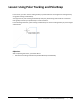
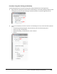
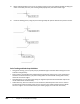
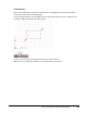
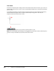
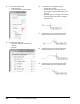
Table Of Contents
- Introduction
- Chapter 1: Taking the AutoCAD Tour
- Chapter 2: Creating Basic Drawings
- Chapter 3: Manipulating Objects
- Lesson: Selecting Objects in the Drawing
- Lesson: Changing an Object's Position
- Lesson: Creating New Objects from Existing Objects
- Lesson: Changing the Angle of an Object's Position
- Lesson: Creating a Mirror Image of Existing Objects
- Lesson: Creating Object Patterns
- Lesson: Changing an Object's Size
- Challenge Exercise: Grips
- Challenge Exercise: Architectural
- Challenge Exercise: Mechanical
- Chapter Summary
- Chapter 4: Drawing Organization and Inquiry Commands
- Chapter 5: Altering Objects
- Lesson: Trimming and Extending Objects to Defined Boundaries
- Lesson: Creating Parallel and Offset Geometry
- Lesson: Joining Objects
- Lesson: Breaking an Object into Two Objects
- Lesson: Applying a Radius Corner to Two Objects
- Lesson: Creating an Angled Corner Between Two Objects
- Lesson: Changing Part of an Object's Shape
- Challenge Exercise: Architectural
- Challenge Exercise: Mechanical
- Chapter Summary

124 ■ Chapter 2: Creating Basic Drawings
Ortho Mode
An alternate method to polar tracking is Ortho mode. When Ortho mode is turned on, your cursor can
move parallel only to the X or Y axes, so you can quickly draw straight lines or move items easily along
the X or Y axes.
In the following illustration, lines were drawn using Ortho mode. The arrow indicates the temporary
override symbol that appears when a temporary override key is being used. In this case, the
temporary override for Ortho mode is active.
Click ORTHO on the status bar or press F8 to turn Ortho mode on or off.
Note: Press and hold SHIFT while drawing or moving geometry to activate the Ortho mode temporary
override. As long as the SHIFT key is pressed, Ortho mode is active.
■