
User`s guide
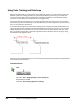
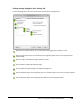
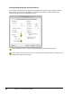
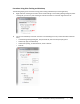
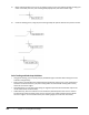
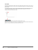
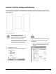
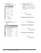
Table Of Contents
- Introduction
- Chapter 1: Taking the AutoCAD Tour
- Chapter 2: Creating Basic Drawings
- Chapter 3: Manipulating Objects
- Lesson: Selecting Objects in the Drawing
- Lesson: Changing an Object's Position
- Lesson: Creating New Objects from Existing Objects
- Lesson: Changing the Angle of an Object's Position
- Lesson: Creating a Mirror Image of Existing Objects
- Lesson: Creating Object Patterns
- Lesson: Changing an Object's Size
- Challenge Exercise: Grips
- Challenge Exercise: Architectural
- Challenge Exercise: Mechanical
- Chapter Summary
- Chapter 4: Drawing Organization and Inquiry Commands
- Chapter 5: Altering Objects
- Lesson: Trimming and Extending Objects to Defined Boundaries
- Lesson: Creating Parallel and Offset Geometry
- Lesson: Joining Objects
- Lesson: Breaking an Object into Two Objects
- Lesson: Applying a Radius Corner to Two Objects
- Lesson: Creating an Angled Corner Between Two Objects
- Lesson: Changing Part of an Object's Shape
- Challenge Exercise: Architectural
- Challenge Exercise: Mechanical
- Chapter Summary

Lesson: Using Polar Tracking and PolarSnap ■ 121
Procedure: Using Polar Tracking and PolarSnap
The following steps give an overview of using polar tracking and PolarSnap to create geometry.
1.
Right-click Polar Tracking on the status bar and click Settings. In the Drafting Settings dialog box, Polar
Tracking tab, you can turn polar tracking on and off and select an increment angle from the list.
2.
You can set a PolarSnap increment as shown in the following list or key in values with direct distance
entry.
■ In the Drafting Settings dialog box, Snap and Grid tab, select the Snap On (F9) option.
■ Under Snap Type, click PolarSnap.
■ Under Polar Spacing, for Polar Distance, enter a distance.
■ Click OK.