® AutoCAD 2012 Preview Guide Design and shape the world around you with the powerful, flexible features found in AutoCAD® software, one of the world’s leading 2D and 3D design applications. With robust 3D tools that can create almost any shape imaginable, AutoCAD helps you intuitively explore design ideas. It offers innovations that can increase design and documentation efficiency, and enables you to more securely, accurately, and seamlessly share those designs with colleagues.
Table of Contents Introducing AutoCAD 2012 ......................................................................................................................... 4 User Interaction and Modernization ............................................................................................................. 4 Performance Improvements ...................................................................................................................... 4 Autodesk Content Explorer........................
Spline Enhancements .............................................................................................................................. 35 2D Array Functionality ........................................................................................................................... 36 Copy Tool ............................................................................................................................................... 39 Layer Enhancements ..................................
Introducing AutoCAD 2012 New and expanded workflows for model documentation, reality capture, and 3D conceptual design help increase productivity with AutoCAD 2012. Explore your design ideas with powerful surface modeling tools. Quickly create documents from a variety of modeling formats, helping to reduce manual documentation workarounds. Capture and import as-built information to jumpstart your design process. Plus, you’ll find a wide range of timesaving enhancements to the features you use most.
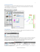
You can locate specific block references or text strings, including block attribute data. Quickly determine how many references there are in a file or find a particular reference across multiple files. Easily drag content from the Content Explorer window into your current drawing. You can also right-click or doubleclick content in the Content Explorer window to automatically open the source file and zoom into relevant objects such as text.
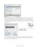
For example, you can filter content so your results show only the specific object types you are interested in. Switch between thumbnail and detail views, specify the icon size, group the results in various ways, and choose whether or not to display text labels and column headers. The Content Explorer searches for content in specified locations that are included in an index.
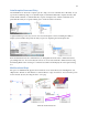
Network Content In addition to searching content on your local computer, Content Explorer can also search one or more network computers. However, it requires the Content Service to run on the network computers and build an index on that machine. This provides a single index that all clients can access and search. Therefore, in order to support searching on network drives, software needs to be installed separately on the network computer.
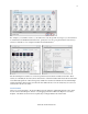
network computer is that on a network computer watched folders need to be shared folders in order for AutoCAD users to be able to access and search them. To add network shares as watched folders, launch the Content Explorer Console, which is located in the Windows Start menu under All Programs > Autodesk > Content Service>Content Service Console. When you choose Add Watched Folder, you’ll notice that only shared folders are available to select.
Autodesk Seek Content In Content Explorer, you can use the Autodesk® Seek web service to browse and search for online content. Find files by manufacturer or via product specs, and insert files directly into your drawing without navigating to an external website. User Interface The updated user interface makes it easier than ever to identify and access frequently used tools. The Home tab includes changes in the Draw and Modify panels. The Insert tab now has Block and Block Definition panels.
AutoComplete Command Entry AutoCAD 2012 now offers auto-complete options to help you access commands more efficiently. As you type in the Command prompt (or use dynamic input), AutoCAD automatically completes the entry with an AutoCAD command or command alias. If you pause, it displays a list of all the commands whose prefix matches what you’ve typed, enabling you to scroll and select from the list.
Using multifunctional grips with dynamic input turned on allows you to edit the object via relevant dimensional values. For example, when you choose the Lengthen option for a selected line, dynamic input dimensions for the total length and the incremental length are displayed. You can use the Tab key to switch between the two values. Similarly, elliptical arcs have been updated to support dynamic input for the major and minor axes.
The Group tool replaces the traditional Object Grouping dialog box with a simple prompt to select objects. You have the option of providing a group name and description. The Ungroup tool ungroups the objects. You can use the Edit Group tool to add and remove objects or to rename the group. These tools are also available from the right-click menu when a group is selected. A Group Selection toggle allows you to control whether objects are selected individually or as a group.
Snap Mode When Snap Mode is on, the cursor no longer snaps to grid points when selecting objects, but does so only when specifying points. External Reference Enhancements AutoCAD 2012 improves the ability to highlight and select externally referenced files. If you pass the cursor over the edge of an attached image, DWFTM, or PDF file, a selection preview frame is displayed, even when frames are turned off.
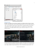
Explore In-Canvas Viewport Control New viewport controls enable you to change viewport settings, views, and visual styles directly on the viewport canvas. The 3D Modeling tab of the Options dialog box includes controls for displaying the in-canvas viewport controls. You can specify the color of the viewport control in the Drawing Window Colors dialog box, which is accessible from the Display tab of the Options dialog. www.autodesk.
UCS Enhancements AutoCAD 2012 provides many enhancements that make the UCS faster and easier to use. The UCS icon has been updated to allow direct manipulation. You can select the UCS icon and then use the multifunctional grips to change the UCS. Easily move the origin, and automatically align the UCS with objects, including curved surfaces and solids. You can rotate the UCS around the X, Y, or Z axis using grips, and without having to access the UCS command.
A new control on the Settings tab of the UCS dialog box enables you to specify whether the UCS icon is selectable. You can access the UCS dialog box from the Coordinates panel of the View ribbon tab when the 3D Modeling workspace is active. Easily access additional UCS controls from a shortcut menu by right-clicking over the UCS Icon. You can modify the shortcut menu to meet your needs using the Customize User Interface dialog box.
3D Associative Array The associative array functionality that is so valuable for 2D documentation is equally useful for 3D modeling. Each of the three types of associative arrays—rectangular, polar, and path—include the ability to array selected objects in 3D space. Use the Level option to specify the number items in the Z direction during or after array creation. Whether you create one- or multiple levels of array objects, you can specify an increment value for row elevation.
Creation Preview A new preview provides a visual cue indicating when a surface or solid is in an intermediate state during creation. For example, as you select profiles to create a lofted solid or surface, an updated preview of the resulting object is displayed with each selection. In addition to solid and surface lofts, the preview is included with the following commands: SURFBLEND, SURFPATCH, SURFFILLET, FILLETEDGE, CHAMFEREDGE, and LOFT.
Chain and Loop Selection AutoCAD 2012 includes new Chain or Loop options to simplify the process of selecting a set of contiguous edges or curves. The new Chain selection option detects if there is a set of contiguous edges within a solid or mesh object, or within or between surfaces. The chain may either be open or closed and is available in the SURFPATCH, SURFBLEND, MESHCAP, and FILLETEDGE commands. The Chain option within the FILLETEDGE command identifies and fillets edges that have continuity.
In addition to the Chain option, the FILLETEDGE and the CHAMFEREDGE command include a Loop option. A loop is similar to a closed chain. After selecting an edge, you can choose which of the potential loops to use. Offset Edge The new Offset Edge tool, available on the Solid Editing panel, enables you to create an offset curve from a planar face or from a surface where all the edges lie on the same plane.
Trimmed Surface Properties The Properties palette for trimmed surfaces is updated to provide more control and flexibility. A new Trims pane displays trim properties for the selected surface. It includes an Edge property, which cycles through the edges and highlights them in the drawing. The new Associative Trim property indicates if the current edge is associative. You can remove the associativity for any given edge.
Solid History Solid history is turned off by default in AutoCAD 2012. With solid history turned off, you can directly edit faces, edges, and vertices of solids. To retain solid history, you can set the SOLIDHIST system variable to 1. 3Dconnexion Support Support for 3Dconnexion devices is improved in AutoCAD 2012. The precision and controllability of 3D mouse movements were further optimized to provide a more superior 2D and 3D navigation experience.
If you choose to install Fusion, you will find an Edit in Fusion tool on the Plug-ins ribbon tab in AutoCAD 2012. You can use this tool to select any of the following 3D objects in your AutoCAD drawing to automatically open it for editing in Autodesk Inventor Fusion: 3D Solid Extruded Surface Lofted Surface Planar Surface Swept Surface Revolved Surface NURBS Surface You will also find the Edit in Fusion option on the right-click menu whenever one of those objects is selected. www.
With Autodesk Inventor Fusion, you will enjoy the freedom of direct modeling with the ability to exercise control over change. Quickly create, delete, or modify features to accommodate your changing designs. Make unique design changes and explore ―what if‖ scenarios. Point Cloud Support Point cloud support is enhanced in AutoCAD 2012. It includes an improved indexing algorithm for generating PCG files in addition to optimized viewing at changing zoom levels.
Document 3D Model Import Import a wide variety of file formats, including CATIA®, NX®, Parasolid, Pro/Engineer®, Rhinoceros®, and SolidWorks®, as a starting point for documenting your designs in AutoCAD. You can access the Import tool from the Import panel of the Insert ribbon tab. In the Import File dialog box, open the Files of Type drop-down list to select the desired file format. While the import operation is in progress, an Import icon is displayed on the status bar tray.
Creating Drawing Views The Base View tool creates a 2D view from the 3D solids and surfaces in modelspace. If there are no surfaces or solids in modelspace, you can select an Inventor project and model (ipt, iam and ipn) files. The Base View tool automatically displays a scaled preview of the model attached to the cursor. As you place the base view on the drawing layout, you can specify options such as type, orientation, and scale. www.autodesk.
A contextual ribbon tab displays relevant controls, which vary depending on the source of the model, AutoCAD modelspace or Inventor. If an Inventor model is the source for the base view, an additional panel is displayed in the Drawing View Creation ribbon tab, enabling you to further control the representation of the model. If the Type option is set to Base and Projected, rather than Base Only, you can automatically create projected views after placing the base view.
After establishing a base view, you can create projected views. Projected views are simply projections of existing views, and they support eight standard view projections: four orthographic and four isometric. Projected views are drawn using the base view’s projection angle (first angle or third angle). During the creation of projected views, a parent/child relationship is formed between the selected view and the projected views.
Editing Drawing Views Using the Drawing View editing tools, you can easily modify drawing views after they’ve been created. When you double-click on an existing view, the Drawing View Editor contextual ribbon tab is displayed. Since child views inherit their properties from their parent, when you edit a parent view, the changes are applied to the parent and all child views. If the selected view is a child view, you can change the scale and style properties to differ from the parents.
Updating Views When changes are made to the source of a drawing view, various notifications appear. The notifications include corner glyphs displayed on the out of date views, a warning badge added to the Drawing Views icon within the status bar tray, and a bubble notification originating from the icon within the status bar tray. You can easily update all views on the layout by selecting a link on the bubble notification.
In addition to the controls in the Drafting Standard dialog box, the Drawing View functionality leverages layers to organize and format geometry. Exporting Layouts The Export Layout tool has been updated to support new 2D View functionality in AutoCAD 2012. You can access this tool from the Save As>Save Layout as Drawing option in the Application menu.
The new Extend leader to text control extends the leader line to the text rather than ending at the text bounding box. www.autodesk.
Dimension Right-Click Menu When you right-click with a dimension selected, you now have the option to Remove Style Overrides. Osnap Enhancements The behavior for Perpendicular and Tangent object snaps is enhanced in AutoCAD 2012 to provide more flexibility. Now, when grip-editing the endpoints of lines or the endpoints and vertices of Polylines, AutoCAD enables you to choose from multiple snap points based on the location of the cursor.
Fillet, Chamfer, Blend, and Join The Fillet and Chamfer tools have been updated to display a preview when passing the cursor over the second object in the fillet/chamfer selection. Now you can confirm and change the radius or distance values before even completing the command. When using the Polyline option, the preview fillet arcs or chamfer lines are displayed for the entire polyline.
The Join tool is streamlined to automatically combine selected objects using typical selection methods such as crossing or picking objects in any order. You are no longer required to select the source object first. Spline Enhancements Splines have been updated in AutoCAD 2012 to support periodic splines. When you specify the Close option for a spline, a periodic spline with C2 continuity between the start and endpoints is generated and the new Periodic property is listed in the Properties window.
The 3D Edit Bar is enhanced to support splines and is accessible from the right-click menu when a spline is selected. It enables you to move the location of a point on the curve, change the magnitude of the tangency at the point, and change the tangent direction relative to the point. 2D Array Functionality Save valuable rework time by establishing and maintaining a set of relationships between arrayed objects, like windows on a building or trusses on a bridge.
Additional options are available in the Contextual ribbon tab and the right-click menu when an array object is selected. You can modify, erase, or transform individual items in an array using the Ctrl key to select the desired objects. You can then use familiar AutoCAD editing tools to erase, move, rotate, or scale those selected objects. Or, use the Replace Item tool to replace selected instances of the array items with other objects.
If you want to change the appearance of all the arrayed objects, there’s no need to start over. You can edit the source object in place. AutoCAD automatically displays the Edit Array contextual tab in addition to the many AutoCAD drawing and editing tools. After making edits to the source geometry, or if you decide against editing the geometry, you can choose to save or discard changes.
Copy Tool The Copy tool includes a new Array option that enables you to create a linear, non-associative array. You can enter the distance between a specified number of copies or enter the number of copies to fit between two specified points. Layer Enhancements A new layer management option enables you to quickly freeze specified layers in all viewports except the current one.
Copy Nested Objects The former NCOPY express tool is integrated into the core AutoCAD software application enabling you to copy objects that are nested in xrefs, blocks, or DGN underlays without having to explode or bind them. Easily access the Copy Nested Objects tool from the Modify panel on the Home ribbon tab.
AutoCAD as the OVERKILL Express Tool, it has been significantly enhanced in AutoCAD 2012 and integrated into the core set of AutoCAD tools. You can access the Delete Duplicates tool from the Modify panel of the Home ribbon tab. The Delete Duplicate Objects dialog box enables you to specify which object properties to ignore, such as thickness or transparency.
DOQ USGS Digital Orthophoto Quads .doq ECW Enhanced Compression Wavelet .ecw HDR High Dynamic Range image .hdr JPEG2000 Wavelet-based compression standard created by the Joint Photographics Expert Group .jp2, .j2k MrSID Multiresolution Seamless Image Database .sid NITF National Imagery Transmission Format .nitf Note: NITF files containing elevation data require AutoCAD® Raster Design software OpenEXR Industrial Light & Magic High Dynamic Range image .
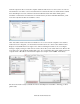
Choose Save As>DWG Convert to display the DWG Convert dialog box. In the DWG Convert dialog box, you can specify the DWG files to be converted, save the list for future use, create new lists, and open or append existing lists. Conversion Setups enable you to specify the conversion properties, such as file format and path options. You can specify how to store the converted drawings, in a zip file or self-extracting executable, for example.
You can save multiple conversion setups, enabling you to easily restore a specific set of conversion properties. For example, you may have a particular client that requires you to save all the drawings to AutoCAD 2000 file format, while another one insists that you purge all the drawings and submit them in AutoCAD 2010 file format. Sheet Set Manager and Vault Integration Autodesk® Vault software manages data creation, simulation, and documentation processes for design and engineering workgroups.
If Autodesk Vault is installed on your system, Vault status icons are displayed in the Sheet Set Manager for the sheet set, individual sheets, and files. The status is also displayed on the tooltip when you hover the cursor over a sheet in the sheet list. The right-click menu in the Sheet Set Manager is updated to include a Vault option. When you right-click on the background of the Sheet List, Sheet Views, or Model Views, you can access the options to Log In and Log Out of Vault.
The Materials Editor has also been updated with labels that make it easier to find controls for creating materials, specifying options, and accessing the Materials Browser. The Information tab in the Materials Editor now includes a field for the material name. Behavior in the Texture Editor is updated to automatically expand the Transforms options, making it easier to find key properties such as position and scale. www.autodesk.
With the evolution of the Autodesk Materials Library, the MATSTATE and MATERIALSPATH variables are no longer necessary and have been removed. AutoCAD WS AutoCAD 2012 extends AutoCAD to the web by integrating tools for direct access to the AutoCAD® WS web and mobile application. AutoCAD WS lets you view, edit, and share DWG drawings through a web browser or mobile device. You can access the AutoCAD WS tools from the Online ribbon tab.
You can use the Upload Multiple Files tool to upload other types of files. For example, you can post relevant plot styles, images, spreadsheets, and other files in addition to your AutoCAD drawings. When you have a drawing open in AutoCAD, you can use the Open Online tool to access and edit the drawing online. AutoCAD automatically uploads the last saved version of the drawing and opens it online in the AutoCAD WS Drawing Editor. www.autodesk.
You can quickly view your online drawings and folders using the Online Drawings tool. The Timeline tool takes advantage of the web’s infinite storage capability to provide a fully detailed design history of the current drawing, including changes by others. www.autodesk.
With your drawings stored online, you can share them with colleagues and clients for accelerated collaboration. The Share Drawing tool enables you to control whether collaborators are limited to viewing the drawing, editing it online, or downloading it to their desktop. And it automatically notifies collaborators with an email invitation. www.autodesk.
In addition to notifying collaborators via email, you can use the Get Link tool to copy a link to the shared drawing, which you can then embed in web pages and documents. The Messages tool enables you to view messages related to the files and folders that you’ve shared or that others have shared with you. www.autodesk.
Customize Installation The installation process in AutoCAD 2012 has been simplified to provide a faster install experience. Dynamic feedback helps you identify inaccurate product information upon entry. www.autodesk.
A product selection page includes descriptions of product components and their install status. Migration and Customization New and enhanced migration tools in AutoCAD 2012 make it easier to migrate your custom settings or reset AutoCAD to the default install settings. The Tool Palette files option in the Migrate Custom Settings dialog box provides improved migration for tool palettes created in previous versions of AutoCAD. Migrating tool palette files now includes tool palette groups.
You can easily access the Migrate Custom Settings dialog box the first time you launch AutoCAD 2012 or from the Windows Start menu (Start>Programs>Autodesk>AutoCAD 2012>Migrate Custom Settings>Migrate From a Previous Release). If, after you have migrated your custom settings to AutoCAD 2012, you wish to return to the default settings, you can use the new Reset tool available from the Windows Start menu (Start>Programs>Autodesk>AutoCAD 2012>Reset Settings to Default).
Managing and exporting tool palette groups in AutoCAD 2012 is easier with the resizable Customize dialog box. Right-click on any palette group to access the Export All option, which was previously only available when right-clicking in an empty area of the Palette Groups list. Plot Files Search Path AutoCAD 2012 provides increased flexibility for managing plot files. You can now specify multiple folders for printer configuration (.PC3) files, printer description (.PMP) files, and plot style (.CBT & .
Autodesk, AutoCAD, Autodesk Inventor, Content Explorer, DWF, DWG, and Inventor are registered trademarks or trademarks of Autodesk, Inc., and/or its subsidiaries and/or affiliates in the USA and/or other countries. [Thirdparty trademarks required by contract.] All other brand names, product names, or trademarks belong to their respective holders.