
Technical information


86 | Chapter 5 Working with Alignments and Parcels
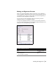
Defining an Object as a Road Alignment
By defining figure geometry as an alignment, all individual geometric com-
ponents (lines, arcs, and spirals) become linked as a single object, and align-
ment data is saved to the database in the project folder.
Because this data is stored in an external database, you can access the align-
ments from all drawings in the project. After you define and alignment, it in
not necessary to draft the alignment in the drawing. All commands that refer
to the alignment geometry reference the database.
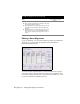
To create alignment geometry
Steps
Use to locate
1 Create a layer on which the alignment centerline is to be
drawn. Use a name such as “CL” for Centerline.
Create and Name Layers
2 Use one of the line drawing options from the Lines/
Curves menu.
Drawing Lines
3 To add curves, use the curve commands from the Lines/
Curves menu.
You can add a curve between two tangents, from the end
of a tangent, and more. These options ensure that the
curve is drawn tangent to the selected lines.
Drawing Curves
4 To draw a spiral, use one of the spiral commands from the
Lines/Curves menu.
Drawing Spirals
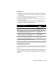
To define an alignment
Steps
Use to locate
1 Draw the alignment geometry. Defining Alignments
2 If you drew an alignment geometry using lines, curves,
and spirals, then select Define From Objects from the
Alignments menu to define the alignment.
If you drew an alignment using a polyline, then select
Define From Polyline from the Alignments menu.
When you define the alignment, you are prompted for
essential information such as the alignment name,
description, starting station, and objects that comprise
the alignment.
Defining an Alignment from
Objects
Defining an Alignment from
a Polyline