
Technical information


Working with the Terrain Model Explorer | 65
In addition to points, you can also build surfaces from DEM files (Digital
Elevation Models), contour, breakline, and boundary data. You can have the
contours treated as individual points where the contour vertices are used as
surface points, or you can have the contours treated as breaklines that
prevent triangulation lines from crossing the contours. Surface TIN lines
typically do not cross contour lines.
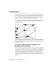
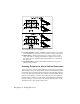
To build a surface accurately, you must provide more information than
points and contours. For example, to prevent surface triangulation across
features such as roads or streams, you can define breaklines. Breaklines are
constraint lines used by the model that represent abrupt changes in the
surface. TIN lines can be drawn to and from breakline vertices, but they do
not cross the breakline.
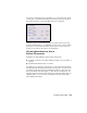
By including boundaries in the surface definition, you can control how the
surface extends to its outer limits, and you can hide internal areas to prevent
triangulation from occurring.
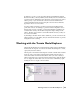
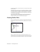
Working with the Terrain Model Explorer
The Terrain Model Explorer consolidates all the surface creation and manage-
ment features in one place. You can use the Terrain Model Explorer to create,
open, build, and view surfaces.
The left pane of the Terrain Model Explorer contains a Terrain and a Volume
folder. To create a new surface, right-click the Terrain folder and choose
Create New Surface from the shortcut menu. After you create a surface, a
surface folder with icon is created below the Terrain folder. Click the surface
icon to display the surface data icons. You can access commands by right-
clicking the icons to display a shortcut menu.