
Technical information


Performing Geodetic Transformations on Points | 57
Performing Geodetic Transformations
on Points
Use the AutoCAD Land Desktop geodesy commands to relate survey data to
mathematical models of the earth.
Using the geodesy commands you can
■ Calculate the latitude and longitude, State Plane, or UTM coordinates of
apoint.
■ Convert point data that is in another coordinate zone into the current
drawing’s coordinate zone when you import points.
■ Convert point data in a project from one coordinate system to another.
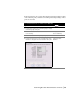
18 In the Data list, choose Point Number and click the Text
button.
19 After {Number} in the text box, press
ENTER to insert a
carriage return.
20 In the Data list, choose Description and click the Text
button.
21 Under Description Keys, select the DescKey Matching On
check box, select the description key file, and select the
Insert DescKey Symbol check box.
22 Click Save and then click OK.
23 From the Labels menu, choose Show Dialog Bar and make
the Desckey point label style that you created the current
point label style.
Selecting the Current Label
Style from the Style
Properties Dialog Bar
24 From the Points menu, choose Create Points
➤ Manual. Creating Points at Selected
Coordinates
25 Select a location in the drawing for the new point.
26 When you are prompted for the description, type UP1A.
The description, UP1A, and the utility pole symbol are
placed with the point, and the point and the symbol are
placed on the specified layers.
To create description keys (continued)
Steps
Use to locate