
Technical information

198 | Chapter 14 Designing Pipe Runs
■ Pipe segments are listed with pipe size (diameter), start and finish invert
elevations, slope, drop, and flow values, as well as roughness coefficients
for use in Manning, Darcy-Weisbach, and Hazen-Williams pipe flow
calculations formulae. Critical flow and depth values for each pipe
segment are listed.
■ Contributing flow data from one or two laterals is listed, with lateral
names, discharge point invert elevations, and flow values.
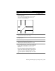
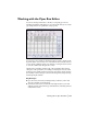
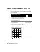
Drafting Finished Pipe Runs in Plan View
After you have configured the final details of a pipe run with the Pipes Run
Editor, you can draft the finished plan pipe run into a drawing. Illustrative
structure blocks and labels for nodes are inserted, and then pipes are drawn
and labeled between nodes. The following illustration shows a finish draft
plan run detail.
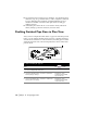
To draft a finished plan pipe run
Steps Use to locate
1 From the Pipes menu, choose Settings
➤ Edit to display
the Pipes Settings Editor dialog box.
2 Under Pipes Drafting Labels, click Plan to establish the
finished plan pipe settings.
Changing the Label
Settings for Finished Draft
Pipes in Plan View
3 Under Node Drafting Labels, click Plan to establish the
finished plan node settings.
Changing the Label
Settings for Finished Draft
Nodes in Plan View