
Technical information

Creating Finished Ground Cross Sections | 179
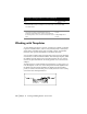
Working with Subassemblies
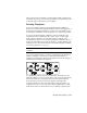
Subassemblies represent optional design elements, such as shoulders or curbs.
You can attach subassemblies to a template at the connection-point-out.
Subassemblies differ from normal template surfaces in that they vary
depending on whether the template is in a cut or fill situation.
The basic design process for a subassembly is to draw and define it, and then
attach it to a template. For more information, see Working with Subassem-
blies in the online Help.
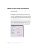
Creating Finished Ground Cross Sections
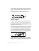
After you draw and define a template, you can use it to generate finished
ground cross sections using the Design Control dialog box.
In addition to controlling the template, use the Design Control dialog box to
make changes to ditches, slopes, and benches, as well as transition align-
ments and profiles. Use other design commands in the dialog box to config-
ure slope settings and superelevation.
Applying Templates to Existing Ground Cross
Sections
Before applying the template to the existing ground cross sections, you must
complete the following minimum requirements:
■ Define a horizontal alignment
■ Sample the existing ground profile from either a surface or from a file
■ Define the vertical alignment for the finished centerline
■ Sample the existing ground cross sections from either the surface or a file
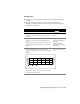
5 From the Cross Sections menu, choose Templates ➤ Edit
Template to add transition points and superelevation
points, as necessary, to the template.
You can also add top surface points to the template that
you can later import into the drawing to use as finished
ground data.
Editing Templates
To work with templates (continued)
Steps Use to locate