
Technical information

176 | Chapter 13 Viewing and Editing Roads in Section View
on. Normal surfaces are the elements of the template that make up the upper
part of the template, such as pavement surfaces, median islands, shoulders
and curbs. A typical subgrade surface is made up of granular substances, such
as gravel.
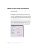
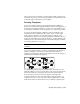
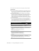
The following illustration shows normal and subgrade surfaces on a
template. Many of the subgrade surface parameters are defined using the
Define Template command instead of the Draw Template command.
Defining Templates
After you draw a template, you can define it by using the Define Template
command. This command can have varying prompts, depending on whether
the template you are defining is composed of normal or subgrade surfaces.
If you define a template with only normal surfaces, specify a finished ground
reference point, a datum line, and connection-points-out. You can also add
subassemblies to the template definition.
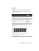
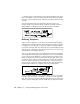
The reference point is the point on the template that controls the placement
of the template horizontally and vertically on the sections. This is usually the
crown of the road. The datum line is compared against the existing ground
surface to calculate the cut and fill areas. The connection-point-out is a point
on each side of the roadway, usually the furthest point from the centerline,
where the defined template stops and match slopes or ditch slopes begin,
based on design control and existing conditions. The following illustration
identifies these elements for a template with only a normal surface.
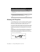
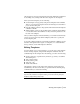
When you define a template with a subgrade surface, you are not prompted
to define connection points, a datum line, or whether to attach subassem-
blies. The connection points are defined automatically at the outer end of the
drawn portion of the subgrade, and the datum lines are generated automati-