
Technical information


166 | Chapter 12 Viewing and Editing Roads in Profile View
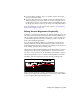
You can control the display of the profile preview graphics, adjust the size
and color of the current PVI marker, and adjust the color of the working
profile and bounding boxes.
IMPORTANT The Vertical Alignment Editor is not linked dynamically to the
drawing. You are prompted to import the finished ground centerline after you
modify it, but you must manually re-import any other alignment offset you
modify to update the drawing.
Generating Reports From Vertical Alignment
Data
Using the Vertical Alignment Editor, you can also generate reports by clicking
the Reports button. For example, you can generate a report that lists the
station, elevation, and curve length at each PVI for the currently displayed
vertical alignment. This report also lists the percent grade that exists between
each PVI. If a vertical curve exists at a PVI, then the report also lists the
vertical curve length.
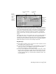
Calculating Vertical Curve Length
You can use the Curve Calculator section of the Vertical Alignment Editor to
analyze information about the current PVI to determine an appropriate ver-
tical curve length. The Curve Calculator is divided into two
sections: a geometric calculator on the left side and a lookup table on
the right.
You must assign a design speed to the alignment (by using the Design Speed
button in the Vertical Alignment Editor) in order to use the lookup table sec-
tion. Double-click a value in the Length column of the lookup table section
to send that value to the Curve Length box on the left side. Then you can
round the value, if needed, and commit the value to the vertical alignment
by clicking the button next to the Curve Length box.