
Technical information


Editing Vertical Alignments | 165
■ Use the geometric calculator section to calculate vertical curve length
based on empirical formulas.
■ Use the lookup table section to calculate vertical curve length based on
defined design speed and lookup tables. To use the lookup table section,
you must first assign one or more design speeds to the alignment by using
the Design Speed button in the top part of the Vertical Alignment Editor.
For more information about the vertical curve calculator, see “Calculating
Vertical Curve Length” on page 166.
Editing Vertical Alignments Graphically
In addition to editing PVI data directly in the Vertical Alignment Editor, you
can edit PVI data in the drawing using the graphical editing commands. You
can use graphical editing commands to move PVIs, to create new PVIs, and
to create finished ground vertical curves, making it possible to design the
entire vertical alignment graphically.
To use the graphical editing commands, a profile must be plotted in the
drawing, and the Show Profile Preview check box must be selected in the
Vertical Alignment Editor Options dialog box. If multiple profiles are plotted
in the drawing, you must select a working profile.
The current PVI is marked with a triangle in the drawing. When you click on
a different PVI in the Vertical Alignment Editor, or use the up and down
arrow keys to move between PVIs, the PVI marker in the drawing is updated.
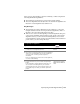
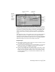
The following illustration shows a selected vertical alignment, the current
PVI marker, and the bounding box that surrounds the working profile.
If the horizontal alignment is visible in the drawing, then the current PVI
marker appears on the horizontal alignment as well as on the profile, making
it easy to compare plan and profile PVI locations.