
Datasheet


Finite Element Analysis
Available in Inventor Professional and Inventor
Simulation Suite
Stress Analysis for Thin Wall Parts
A new thin shell element provides faster analysis than
standard 3D tetra elements when analyzing thin-walled
or constant-thickness parts.
Feature Suppression for Stress Analysis
The Stress Analysis environment now has the ability to
maintain a unique set of feature suppressions that are
independent of the part’s original part or sheet metal
environments. This allows simplifying geometry to
provide more effi cient meshing.
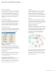
Multiple Time Step Analysis
Analysis based on loads at multiple time points in
a dynamic simulation cycle can now be exported at
once, eliminating the need to switch back to dynamic
simulation for each time step. Users can quickly view
the analysis output at each time step and see the
assembly update to the corresponding position.
Frame Design
The design of welded frames using skeletal reference
geometry is easier and faster in Inventor 2008. This
enables the design of larger, more complex frames
and simplifi es the modifi cation
of frame member
characteristics during
the design process.
Parametric
Frame Layout
With Inventor 2008, frame
generator adopts a new layout
technology similar to that used
in tube and pipe routing. Based on the
generation of a 3D reference wireframe—called
the Frame Reference Model—the new approach
provides full-model associativity and lets designers
use any combination of sketch, part, and assembly
geometry. In addition, designers can now reorganize
individual sections into separate subassemblies, using
Promote and Demote commands, to refl ect the actual
manufacturing sequence.
Improved Cut Treatments
Designers can now create frame designs based on
geometry from diff erent parts and assemblies with full
support for end treatments irrespective of the origin
of the skeletal geometry. Cut treatments are displayed
as separate items in the browser with their own custom
properties for extend length and manufacturing notes.
Improved Frame Editing
Substituting a frame section with a diff erent standard,
type or size is simpler and faster. The Change tool has
new lock options allowing designers to quickly edit
multiple section pieces at the same time—even if there
are diff erences in the section or size in the group that
users want to edit.
Bent frame members
A new Merge option on the Insert tool creates single
swept frame elements when working with edges.
Other Enhancements
Standards
Frame generator includes additional standards support
including GOST and AFNOR sections.
Performance
Performance is substantially improved, especially when
working with large frame designs, and the 3D preview
is also faster.
Design Accelerators
Several of the Component Generators and Mechanical
Calculators have been updated with new interfaces and
interactive dynamic preview.
Shaft Generator
The Shaft Generator has been redesigned to
incorporate full 3D preview with optional 2D
diagrammatic preview. The 3D preview includes 3D
Grips, allowing designers to interactively alter the
length and diameter of individual elements. Using
the Element area of the generator dialog, designers
can quickly select the element type—cylinder, cone
or n-sided—as well as specify internal geometry, end
treatments, and
element features
such as keyways,
through holes, and
retaining rings.
Shaft parameters
are automatically
transferred to the
calculations tab
enabling designers
to interactively
defi ne loads,
bending moments,
and torques then
calculate rigid stress
analysis under the
set conditions.
13
Autodesk Inventor 2008
Technical What’s New