HPS-120 HandyPort-Serial Wireless Solutions in your Hand User’s Manual
Table of Contents 1. 2. INTRODUCTION ....................................................................................................................3 1.1. FEATURES .........................................................................................................................3 1.2. PACKAGE ..........................................................................................................................3 SPECIFICATIONS............................................................
1. Introduction Thank you for purchasing a HandyPort-Serial. The HandyPort-Serial can be used as a component in many types of systems allowing them to communicate wirelessly with other Bluetooth products such as PC-cards, laptops, handheld computers, mobile phones and other HandyPort-Serial. The HandyPort-Serial is a suitable component in new products as well as in existing products. 1.1.
2. Specifications 2.1. General Baud Rate Up to 115.2kbps (Recommend above 2.4kbps) Supports 1.2/2.4/4.8/9.6/19.2/38.4/57.6/115.2kbps Coverage Up to 100 M Connection Point-to-Point Signal DCD, TxD, RxD, GND, CTS/DSR RS-232 Interface D_SUB 9 Pin Female Standard Bluetooth Specification Version 1.1 Frequency 2.400 ~ 2.4835GHz Hopping 1,600/Sec, 1MHz Channel Space Modulation GFSK, 1Mbps, 0.5BT Gaussian Tx. Power Max 20 / Typical 16dBm (Class 1) Rx.
2.2. RS-232 Interface 2.2.1. Pin-out 2.2.2. Signals Pin Number Signal Direction Description 1 DCD Output Data Carrier Detect 2 TxD Output Transmitted Data 3 RxD Input Received Data 4 DSR N/A (Input) Option: Data Set Ready 5 GND N/A Signal Ground 6 DTR Output Data Terminal Ready 7 CTS Input Clear to Send 8 RTS Output Request to Send 9 Vcc (Remark1) Input (Remark1) Power Supply Remark1) The default hardware configuration is for using CTS.
2.4. Display Status The following is status LED information. z OPR (Red): When HPS-120 is powered on, it is turned on or flashing. z LNK (Green): When a wireless link is on, it is turned on. If HPS-120 is in the configuration mode, it will be flashing every second. 2.5. Reset Button The RST button has the following functions. z Enter / Exit the configuration mode z Restore the factory settings z Disconnect and reconnect a wireless connection. 2.5.1.
3. Hardware Installation 3.1. Hardware Description RST Button Screw RS-232 Connector OPR LED LNK LED DC In Jack USB Cable for Power Antenna / Connector 3.2. Power Supply You can supply power to the HPS-120 as follows: Use an AC/DC converter (Output Power: +5 ~ +12Vdc / 300mA). th You can supply power via 9 pin of D_SUB 9 Pin connector. 3.3. Install Procedure Step 1: Assemble a provided antenna to HPS-120 body. Step 3: Power on.
4. Usage You can change the configuration of HPS-120 using Hyper Terminal. 4.1. Hyper Terminal Settings Baud Rate: 9600 bps / Data Bit: 8 / Parity Bit: None / Stop Bit: 1 / Flow Control: None / Emulation: VT100 4.2. Configuration 4.2.1. Start Configuration Step 1: Plug a HPS-120 into a COM port of PC. And Power it on. Step 2: Open a Hyper Terminal and set it up. Step 3: Push the RST button on HPS-120.
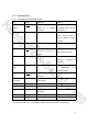
4.3. Command Set 4.3.1. Command List for Local Device Item 1. Syntax Connecting AAddr address Description Set a address Remarks remote for a device A 3. COM port BBaud Rate CCOM Port and remote wireless BD_ADDR always need to connection. be difference. Change the baud rate Baud Rate - 0: 1200, 1: 2. Baud rate local 2400, 2: 4800, 3: 9600, 4: 19200, 5: 38400, 6: 57600, 7: 115200 This is only valid in connection mode 2. 4.
4.3.2. Command List for Remote Device To change the configuration for a remote device via over-the-air, firstly you have to use a command “O” at the local device. The following are a procedure for changing configuration of remote device via over-the-air. z Configure a remote device at the local device. z Save changes at the local device. z Make a connection between the local device and remote device (Automatically).