V30 Diagnostic Computer USER MANUAL Version 1.65 Copyright ©2009 by Tech. Inc.
User Manual Statement Copyright © 2008 by AUTOBOSS TECH. INC. (short for "AUTOBOSS"). All rights reserved. No part of this publication can be reproduced, stored in a retrieval system, or transmitted in any form or by any means, electronic, mechanical, photocopying, recording or otherwise, without the prior written permission of AUTOBOSS. The information contained herein is designed only for the use of this unit. AUTOBOSS is not responsible for any use of this information as applied to other units.
User Manual V30 User Manual instructions Please read this user manual carefully before using the scanner. The current user manual is based on the current features and functions available. Any new added features and functions of V30 Diagnostic Computer will be added to the user manual in the future. Updated versions of user manual will be available to download at AUTOBOSS website (http://www.AUTOBOSS.net).
User Manual CONTENTS 1 Introduction .......................................................................................................................................1 1.1 FUNCTION AND FEATURE ..........................................................................................1 1.2 LAYOUT OF MAIN UNIT .............................................................................................1 1.3 TECHNICAL PARAMETERS .............................................................................
User Manual 1 Introduction 1.1 Function and Feature OE level coverage for European, Asian, American and Chinese cars Supports Multi-language CAN-BUS with high/low speed One OBDII connector for all CAN bus systems Frequent software update online High resolution VGA color TFT display Windows CE Operating System Quick Test function to test most vehicle systems Demo Mode for many OEM’s Data graphing Self-check function 1.
User Manual 1.3 Technical Parameters CPU: SAMSUNG ARM9 2410A, 200MHz; Memory: 64M; Flash card: SD card, 1G Display: 5.6” VGA (640×480) ultra bright TFT; Power supply: DC 8~12V, AC 110~250V 50Hz; Port: Diagnosis port, COM port, USB port, Power Port; Operating system: WINDOWS CE; Storage temperature: -30~90ºC; Working temperature: -10~80ºC; Humidity: <90%. 1.
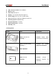
User Manual Picture Item Description Name: Touch pen / Stylus Function: For touch screen Quantity: 1 operation Name: Main Cable Function: Connect the main Quantity: 1 unit & connectors for diagnosis Name: BENZ-38 connector Function: Used for testing Quantity: 1 Mercedes-Benz equipped with vehicles a circular 38-pin DLC Name: BMW-20 connector Function: Used for testing Quantity: 1 BMW vehicles equipped with a 20-pin DLC Name: Chery/Fiat -3 connector Function: Used for testing Qua
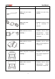
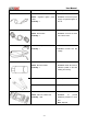
User Manual Picture Item Description Name: Kia-20 connector Function: Used for testing Quantity: 1 KIA vehicles equipped with a 20-pin DLC Name: Mazda-17 connector Function: Used for testing Quantity: 1 MAZDA vehicles equipped with a 17-pin DLC Name: TOYOTA-17 connector Function: Quantity: 1 TOYOTA/LEXUS vehicles Used for testing equipped with a semi-circular 17pin DLC Name: TOYOTA-22 connector Function: Used for testing Quantity: 1 Toyota and Lexus vehicles with a rectangular 22-pin DLC
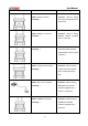
User Manual Picture Item Description Name: BENZ-4 connector Function: Used for testing Quantity: 1 Mercedes-Benz vehicles before 1997 with flash codes.
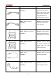
User Manual Picture Item Description Name: Cigarette lighter power Function: Provide the power cable supply via cigarette lighter on Quantity: 1 the car Name: Serial cable Function: Connect the main Quantity: 1 unit and PC base Name: DC adaptor Quantity: 1 Function: Provide 12V DC voltage Name: SD Card reader Function: Read SD card for Quantity: 1 software update or SD card reading and writing Fuse 5A 30*6 Spare parts Fuse 5A 20*5 Spare parts Name: main unit rubber boot Function: Qu
User Manual Picture Item Description Name: Benz-14 pin connector Function: Quantity: 1 Mercedes-Benz Sprinter Used to test Note: Optional Function: Name: Chrysler-16 connector Chrysler Quantity: 1 protocol Used car to with test CCD Note: Optional NOTE: Configuration varies as per software package. For complete configuration, please refer to the relevant packing list.
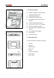
User Manual 2 Operation 2.1 Power Supply & Cable Connection 2.1.1 Power Supply There are 3 ways to get power for V30 Diagnostic Computer. From: ① Vehicle DLC, no external power supply needed ② Cigarette lighter ③ Battery 2.1.2 Cable Connection How to get power supply: 1. Cigarette lighter plug 2. Battery cable 3. Battery 4. Main cable 5. Main cable adaptor ① main unit if DLC is not self-powered. ② 8. Power port 9. Cigarette lighter No external power supply needed if DLC is self-powered.
User Manual 2.2 Interface Instruction 2.2.1 Starting Interface The screen shown on the left picture will appear on the screen after the scanner is switched on. 2.2.2 Touch Screen Calibration Several seconds after power is switched on, the screen will go into calibration mode. Click anywhere on the screen to start calibration if necessary. Note: Just wait for several seconds until the diagnosis program runs if screen calibration is not required.
User Manual 2.2.3 Diagnose Program After entering [Diagnose], you will enter the diagnostic screen where you can select the region of vehicle manufacturer required: China, Europe, Asia, America and Others (OBDⅡ/EOBD). Europe: This section includes the diagnostic programs for European vehicles. Asia: This section includes the diagnostic programs for Asian and Korean vehicles. America: This section includes the diagnostic programs for US vehicles.
User Manual 2.2.4 System Setting Click on the button [Setting] to enter settings for language, time, download and unit. 2.2.4.1 Language Setting V30 supports Multilanguage. Choose any language needed under [working language] and press [OK] to finish language setting. 2.2.4.2 Time Setting Click on [Set time] to enter the menu for time selection. By clicking on signs of “▼”or“▲”, numbers will increase or decrease correspondingly. Click on the button [Set time] to finish setting.
User Manual 2.2.4.4 Display Data Stream in British Unit Data stream will be displayed in British unit after [British unit] is chosen.
User Manual 2.2.5 Self Test This is for hardware checking. Click on the button [Self check] and any hardware faults will be displayed. Please contact technical support if a hardware problem is reported. If there are no hardware errors, the checking result will be “System Self test report: No error found.” 2.2.6 PC LINK PC Link is not available at this time. The V30 diagnostic computer can be operated via PC/Laptop by installing PC LINK software.
User Manual 2.2.8 Power Off Click on [Exit] of main menu to switch off the V30 main unit. Warning dialog box “Do you want to shutdown this device?” will popup. Click [No] to return to the operating menu. Click [Yes] to switch off the main unit.
User Manual 2.3 Software Upgrading 2.3.1 Download and Install “V30 Update Client” Step1: Visit AUTOBOSS website at http://www.AUTOBOSS.net Step2: Enter English website Step3: Click on [V30] under the button [Download] to enter download screen as shown in left image. Step4: Click on the option [V30 Update Client] to download the update client to your PC. A file named V30setupEn.exe will be saved in your PC.
User Manual Step 5: Double click on this file to install “V30 update client” step by step until you see the image shown on the left. Note: Just click on the button [Next] in each step during the installation. We advise you to keep everything as default. Please remember to input your name and company name. After finishing the installation, you will see the icon shown below on your desktop. . Download of “V30 update client” is finished. 2.3.2 Check V30 S/N and Password Check the S/N: Please refer to 2.2.
User Manual 2.3.3 Upgrading Instructions 2.3.3.1 Run V30 update client program Step1: Take out the SD card from main unit, plug it into the USB SD card reader and connect to PC. Step 2: Double click to run the V30 update client program on your PC and go to update screen as shown in Fig 2-1. Fig 2-1 Login screen 2.3.3.2 Login the Server (1) Input the serial number and password then click on the [OK] button to connect to server. It takes some seconds before the download is finished like Fig 2-2.
User Manual (4) After download is finished, all updates available will be displayed as shown in Fig 2-3. (5) The update client will automatically identify new updates available for your V30. Fig 2-3 Program list screen 2.3.3.3 Modify Password After initial login, users can change original registered password. Operation instruction: (1) After inputting the serial number, click on [Modify password] as shown in Fig 2-4 to go to Fig 2-4 Modify password the next step as Fig 2-5.
User Manual 2.3.3.4 Input Customer Information You must fill in your personal information when you first login to V30 update client; otherwise you will not be able to download updates. Operation instruction: Click on the button [Customer info] after login succeeds. You can see the screen as shown in Fig. 2-6. Input your information to the relevant spaces and click [OK] to save the information. Fig2-6 Input customer info screen 2.3.3.
User Manual 2.3.3.6 Update (1) Take out the SD card from V30 main unit; (2) Put the SD card into SD Card reader; (3) Connect the Card-Reader to PC USB port; (4) Select the SD card driver on the top-right side of software installation screen as shown in Fig.2-9; Fig.2-9 Software installation screen (5) Click on the button [Update], the selected programs already downloaded to your PC hard drive will be installed on SD card automatically. Note: Make sure the update destination is the SD card driver.
User Manual 2.4 USE YOUR PC TO PRINT SAVED FILES FROM SD CARD (1). Insert SD card in SD card reader (2). Plug SD card reader into USB port of PC (3). Window as shown will pop up, select “open folder to view files” press “OK” NOTE: You can also obtain a printout by pressing “Print” with the optional mini printer installed on the V30. (4).
User Manual (6).
User Manual 3 Test Procedure 3.1 Engine ECU Testing Methods 3.1.1 Testing Description (1) Power up and turn on the scanner; (2) Click on [Diagnose] [Europe] to enter screen as shown on the left image; (3)Select diagnostic program Click on [VW], for example, to enter software version selection screen shown in the left image. Note: Program descriptions will be displayed under the version information. (4) Select a version such as V3.1 and click on [OK] as shown in left image.
User Manual (6) Select system: [Common system Auto-Scan]: Test the common-use ECU automatically; [All system Auto-Scan]: Test all ECU automatically; [Common]: by choosing this item, all common-use ECU will be displayed on the screen, users can then select ECU required accordingly; Other systems: Enter the systems as per relevant ECU type. (7) Click on [Common] to enter the screen shown on the left. Select [01-Engine] to enter the screen with the following functions.
User Manual ① [01-Interrogate control unit versions] Click on [01-Interrogate control unit versions] to see the information of control unit as shown on the left. Note: Read out old ECU codes with this function when performing ECU coding. ② [02-Interrogate fault memory] To display the DTC saved in the current control unit, click [02-Interrogate fault memory]. Please refer to the left image.
User Manual The window of “Basic setting!” in left image will popup after Basic Setting is done. [Input]: continue to Input number; [Back]: Back to the Function Menu. Note: Under basic setting mode, you can perform solenoid and engine control unit adaptation without starting the engine, or finish λ control process self-adaptation when engine starts. Also you can check faults or ignition timing by connecting or disconnecting λ control.
User Manual ⑧ [08-Read measuring value block] Click on [08-Read measuring value block] to enter screen shown in left image. Please input the relevant channel number, and click on [OK] to read data stream information. Note: For channel definition, please refer to relevant technical manual. The left image is the data stream of Group 01.
User Manual ⑩ [10-Adaptation] Click on [10-Adaptation] to enter the screen for inputting channel number as shown in left image. Note: Self-adaptation includes: self-study during idle, service reset, IMMO adaptation and so on. You should login first for some of the functions. For login methods, please refer to [11-Login procedure] on page 26. After inputting the relevant channel number, click on [OK] to enter the screen as shown in left image.
User Manual After inputting the new value, new adaptation value will be displayed on the screen. If no error is found, please click on the button [Change] to go to the next step. Last step: Click on the button [Save] to save the new adaptation value and go back to the self-adaptation screen.
User Manual [11-Login procedure] To perform adaptation in some group, login will be needed first. Just click on the button [11-Login procedure], input the code number and then click on [OK]. Note: Login is required when performing functions such as ECU coding, change channel adaptation and IMMO, etc. [15-Write VIN] rd Volkswagen/Audi uses the 3 generation anti-theft technology, if you change engine control unit and instrument cluster at the same time you must rewrite the VIN code.
User Manual Order Information AUTOBOSS TECH. INC. Address: No.1102, Building B of Futian Tian'an Hi-Tech Venture Park, Futian District, Shenzhen, China Email: marketing@autoboss.net Tel: +86-755-8832 3051 / 8832 3052 / 8832 3053 Fax: +86-755-8832 3012 Website: http://www.AUTOBOSS.