C3-RS1100 OLED PROFESSIONAL 2-WAY 915 MHz. OLED REMOTE CAR STARTER & 6 CHANNEL ALARM SYSTEM With Built-in Temperature Sensor And Two Way Serial Port Data Link INSTALLATION MANUAL Compatible THIS PRODUCT IS DESIGNED FOR PROFESSIONAL INSTALLATION ONLY C3 RS1100REV.
TABLE OF CONTENTS: INSTALLATION DIAGRAMS H1: 6 PIN HEAVY GAUGE WIRING CONNECTION H1/1 Violet Wire – Starter Output H1/2 & H1/3 Red Wire – +12V Power Input H1/4 Yellow Wire – Ignition 1 Output H1/5 Pink Wire – Ignition 2 Output H1/6 Brown Wire – Accessory Output (Heater /ACC Output) H5: 5 PIN WHITE WIRE HARNESS H5/1 Red / White wire – Parking Light Relay Power Input H5/2 White wire – Parking Light Relay Output H5/3 Black wire – System Ground H5/4 Brown wire – Siren Drive Output H5/5 Red wire – System Power H
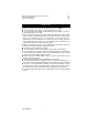
Mechanical Neutral Safety Switch Considerations Park/Neutral ECM Input Key In Sensor Circuits 31 31 32 INTRODUCTION This Remote Starter with Alarm and Keyless Entry System has been designed to be installed on fuel-injected vehicles with an automatic transmission ONLY. n Never install this remote starter on a manual transmission vehicle. n This system must be installed and wired through a safety switch so it will not start in any forward or reverse gear.
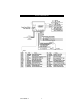
INSTALLATION DIAGRAM C3 RS1100REV.
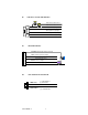
H1 6 PIN HEAVY GAUGE WIRE HARNESS 20A 20A Red: Remote Start Power 1 Red: Remote Start Power 2 Violet: Starter (+) Output Pink: Ignition 2 (+) Output Yellow: Ignition 1 (+) Output Brown: Acc/Heater (+) Output H5 5 PIN WIRE HARNESS Red/White: Parking Light Relay Power Input White: Parking Light Relay Output Black: System Main Ground (-) Brown: Siren (+) Output Red: 12v + Battery Power H4. 3 PIN, DOOR LOCK CONNECTOR 1. Blue Wire ( - ) Unlock Pulse (+) Lock Pulse 3.
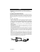
WIRING Keep wiring away from moving engine parts, exhaust pipes and high-tension cable. Be sure to tape wires that pass through holes on the firewall to prevent fraying. CAUTION: Do not connect the wire harness to the control module until all wiring to vehicle is complete. H1: 6 PIN HEAVY GAUGE WIRING CONNECTIONS: Remember that what the system does to start a vehicle is to duplicate the functions of the ignition key switch! Below, we will explain the three basic functions of the ignition switch.
Red Wire (2) — +12V Power Input Remove the two 20A fuses prior to connecting these wires and do not replace them until the satellite has been plugged into the control module. These wires are the source of current for all the circuits the relay satellite will energize. They must be connected to a high current source. Since the factory supplies (+) 12V to the key switch that is used to operate the motor, it is recommended that these wires be connected there.
been designed for use with all C I 3 compatible components. C I 3 Telematics system is available at any authorized Autopage dealer. This port will only operate correctly with Autopage C3 I-Datalink Modules . H3. 2 PIN WHITE CONNECTOR (THE LED STATUS INDICATOR): The led indicator status should be mounted in a highly visible area such as top of the dashboard, on top of the shifter console or on the dashboard face. Leave at least 6mm space behind the mounting location for LED housing.
H7. 4-PIN BLACK CONNECTOR. – TWO-WAY TRANSCEIVER/ANTENNA MODULE The Two-way transceiver/antenna mounting location should be the upper left or lower left corner of driver’s windshield. For optimum range we suggest that the antenna be mounted Antenna tip facing down. Warning! Do not mount in such a manner that it obstructs the driver’s view. - Remove the protective tape backing. - Carefully align the two-way transceiver/antenna and apply to windshield.
H6: 22 PIN WIRE CONNECTORS: H6/1 BROWN/BLACK WIRE: 200 mA (-) Ground Output When Running. This wire provides a negative output during the remote start process. It can be used to operate by-pass modules that may be required in your installation. This wire will provide ground once the remote start process has been initiated and will remain grounded while the engine is running H6/2 GRAY/BLACK WIRE: 200 mA (-) Second Starter Output. This line can be used if a second starter line is needed.
This output is for a Key Sense wire by -pass that some Chrysler and Toyota vehicles need to activate remote start. This wire comes on when remote start is activated and stays on for 20 seconds. H6/4 White / Bule wire – (-) Instant Start & Turn Off Input – This wires activates and turns off the remote starter each time it sees a momentary ground signal. Normally used for testing during installation or when activating the module from an after-market system.
When the BLACK/WHITE wire is grounded, the remote start unit is operable. When this wire is open from ground, the remote start is disabled. 1. The optional “remote start toggle switch” can be added on to temporarily disable the Remote Start Device, it can prevent the vehicle from being remote started accidentally. This feature is useful if the vehicle is being serviced or stored in an enclosed area. To disable the remote start, move the optional remote start enable toggle switch to the OFF position.
Also on certain BMW, Mercedes Benz, Jaguar and Volkswagen cars, you can use this unique timed output to allow remote closure of all power window and sunroof without the need for an external module! H6/12 Blue / Black wire – (-) 200mA Accessory 2 Output – This wire provides a 200mA (-) ground output. This output will energize when the remote start is activated, go away while the starter is cranking, and then come back on when the vehicle has started successfully.
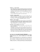
This wire provides a 200mA (-) ground output that becomes active 4 seconds before the remote start unit initialize, and remains grounded while running. Ignition 3 output: + 12 V Constant Some newer vehicles use a third Fused 25A Capable 87 ignition wire which is required to start Yellow Wire and keep the vehicle’s engine 87a 86 85 running.
Matching Resistor VAT wire (#1) 87 YELLOW wire 85 87a 86 To + 12 V VAT wire (#2) 30 Ignition Switch VATS control Module H6/15 Green wire – Negative Door Switch Sensing Input (Zone 3) – This wire is the ground trigger input wire for negative door pin switch. This wire is connection for "grounding" type factory door pins locate the "common wire" that connects the door pin switches. Make the connection of the GREEN Wire here.
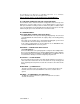
The WHITE/BLACK wire provides an instant shutdown for the remote start, Hood Pin Switch whenever it is grounded. Connect the wire to the hood pin switch previously installed. This wire must be routed To: Alarm instant though a grommet in the firewall and To: White/Black Wire / trigger Blue wire Negative safety connected to the hood pin switch. If the pin switch is to be used with an Diode Diode alarm system, connect this wire with diode.
POSITIVE TRIGGER DOOR LOCK SYSTEM 5-WIRE ALTERNATING DOOR LOCK Blue Wire Door lock +12V Green Wire Master Door Lock Switch Locking Master Switch Red (not used) Splice 86 87 3 Pin Plug To Alarm 87a Cut the Existing Unlock Wire 30 85 Green Wire Door Unlock X + 12V Splice To Exiting Door Lock Relay Red +12V 86 X 87 87a Cut the Existing Lock Wire 30 To Door Lock Motor 85 Blue Wire To Slave Door Lock switches VACUUM OPERATED CENTRAL LOCKING Green Wire 86 Door Switch X Cut 87a 30 8
2 STEP DOOR UNLOCK WIRE CONNECTION FOR GROUND SWITCHED DOOR LOCKS H10/14 : 20-Pin Plug From Alarm +12V H10/12: 20-Pin Plug Pink Wire From Alarm OEM Door Master Lock Switch Pink Wire Unlock Lock OEM Door Master Lock Switch 87 Unlock 86 87a Existing Pos. Unlock Wire Existing Neg. Lock Wire Unlock Wire Lock 85 30 Existing Neg. Green Wire Door Lock 2 STEP DOOR UNLOCK WIRE CONNECTION FOR POSITIVE SWITCHED DOOR LOCKS + 12V Existing Pos.
4. Press the transmitter button corresponding to the feature you want to program. Press Transmitter Button One Chirp / LED one pulse Factory Default Setting Two Chirps / LED two pulses Three Chirps / LED three pulses Active arming Passive arming without passive door locking Passive arming with passive door locking. 1 2 Automatic Rearm off 3 Instant Door Ajar error chirp 4 All Confirmation chirps on 5 6 7 8 Automatic Rearm on 45 seconds delay Door Ajar error chirp.
1 Turn the Ignition switch ‘ON/OFF’ 3 TIMES and stay in OFF position. 2 Push the Valet switch 5 times (holding in on the 5th push) until two chirps with one long chirp is heard then release the valet switch. You are now in the Alarm feature “B” programming mode. 3 Press and release the transmitter button corresponding to the feature you want to program.
(The system Can not The shock sensor be Arm with the will be engine running) by-passed upon engine running. (The engine will run by itself after the ignition is turned off) The shock sensor by-pass three minutes after armed. (The engine will run by itself after the ignition is turned off) Press and buttons at the same time to control Engine run time for one minute and the shock sensor will be by-passed upon engine running.
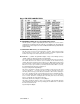
2 H6/6 Brown / White Wire = (-) 200mA Horn Output 3 Fahrenheit display for Temperature Override Without Password Pin Code H6/7 Black / Green Wire Channel 4 Output = Pulsed output 4 H6/6 Brown / White Wire = Factory Security Rearm Signal Output Celsius display For temperature Override With Password Pin Code H6/7 Black / Green Wire Channel 4 Output = Latched output 5 + 6 + H6/22 Black / Red Wire Channel 5 Output = Momentary output H6/22 Black / Red Wire Channel 5 Output = Latched output 7 + H6/1
Note 1 : If your built-in timer controls window/sunroof closure in your car DO NOT change the timer setting! This requires installer -only programming. Changing the value will adversely effect operation and may cause damage. Note 2: Momentary output = The momentary output selection will send a negative signal from the Channel 4 output immediately when the channel 4 ( 5,6 ) button is pressed and will continue until the button is released.
Program: 1. Press and release the transmitter button twice, [2] LED flash, [2] siren/horn chirp to indicate you are in features “Password pin code programming mode”. 2. Within 5 seconds, press and release the valet Switch 9 times. 3. Within 15 seconds of the last entered 9ths digit, turn the Ignition Switch to “ON” position. 4. Within 15 seconds press the valet Switch twice. 5. Turn the Ignition Switch to “OFF’ position. You will note the LED flashing nine times, pause and then flash two times, pause.
6 7 8 TemperatureControl Starting OFF + + + Temperature-Co ntrol Starting “ON” 0 ºF / -18 ºC Temperature-Cont rol Starting “ON” 15 ºF / -9 ºC Press button = Activate Remote Start. Press button = Activate Remote Start. H6/4 White/Blue wire= 1 pulse activate H6/4 White/Blue wire = 2 pulse activate Press + button = Activate Remote Start. H6/4 White/Blue wire = 3 pulse activate Exit: Turn Ignition to 'ON' position, or leave it for 15 seconds.
6 + “TEST” Mode for Zone 2 / instant tri gger & Zone 3 / Door trigger 7 + + 50 RPM DBI ONLY No RPM learning - 50 RPM DBI ONLY No RPM Learning or < 50RPM 8 9 + + “TEST” Mode for Zone 1 & Zone 4 (2 Stage Shock Sensor) Automatic Transmission Exit: Press the confirm exit. button on the transmitter. 3 long chirps & 3 parking light flashes will ** This will be used when connected to an Autopage CI3 compatible Two-way data module that will recognize the tach signal from the vehicle.
CHECK LEVEL PROGRAMMING: (TEST and ADJUST) 1. Press button once on the transmitter to start the vehicle. 2. If everything goes well: a. Press button once on the transmitter to stop engine running. You have been completed this programming successfully. b. Press button on the transmitter to exit the program mode. There will be 3 long chirps & 3 parking light flashes for confirmation. 3. If the crank time is too long, (Engine already successfully running, but still cranks): a.
b. Press button on the transmitter to set proper “Start Timer”. The chirp & LED pause will confirm entry. (Increase “Start Timer ” is necessary.) c. Repeat steps 1 – 4. Timer Checking Type 1. Turn the Ignition 'switch ‘ON/OFF’ 3 TIMES and stay in OFF position. th 2. Push the Valet switch 11 times and hold it on the 11 push until five chirps with a long chirp is hearing then release the valet switch. 3. Press the transmitter and buttons at the same time to set the “Timer Checking Type”.
b. Test the Zone 1 & Zone 4 / Two S tage Shock Sensor (Connected to H9 4 Pin Plug): Press and release the transmitter and buttons at the same time again. [2] LED flash, [2] siren/horn chirps to indicate your are in the shock sensor (connected to H9 4 pin plug) test mode. 1. Activate the warn-away (first stage of the shock sensor / Zone 1), system will emit a short chirp. 2. Activate the full alarm (second stage of the shock sensor / Zone 4), system will emit a long chirp. 3.
5. The remote start feature programming has not been programmed to start the vehicle. The remote start must be programmed how to start the vehicle. SHUTDOWN DIAGNOSTICS The unit has the ability to report the cause of the last shutdown of the remote start system. Enter: 1. Turn the Ignition switch to ‘ON position. 2. Press the button on the transmitter. 3.
3. NEUTRAL START SAFETY TEST: 1. Set the vehicle parking brake. 2. Block the drive wheels to prevent vehicle movement. 3. Sitting in the vehicle, turn the ignition switch to “ON” or “RUN” position. But do not start the engine. 4. Step on the brake pedal and shift the gear selector into “DRIVE” (D). 5. Put your foot over the brake pedal but do not press down on it. Be ready to step on the brake to shut down the Remote Start Device. 6. Start the vehicle using remote transmitter. a.
Optional Enable Switch Ignition P To Neutral Safety Switch Input wire Black/White (H10/1) R Electronic Control Module (ECM) Solid State, Do Not Measure Resistance 1 N D 2 KEY IN SENSOR CIRCUITS: If the vehicle you are working on does not have or you cannot locate the ECM reference wire, there are two alternatives available.
(H6/8) of the Remote Start Unit. F. Connect terminal 86 of the relay to a fused + 12 volt constant battery source. G. Connect terminal 87 of the relay to the Chime Module side of the previously cut wire in step D. H. Connect terminal 85 of the relay to the Drivers Door side of the pin switch wire previously cut in step B. Note: A second 4003 series diode may be required to maintain the integrity of the hood open, shut down circuit. If this is the case, it must be installed as shown in the diagram above.
Available At an Authorized Autopage Dealer The RS-1100 is CI3 Compatible It is recommended to have a minimal digital service plan on your cell phone. C3 RS1100REV.
BLANK PAGE C3 RS1100REV.
960 Knox Street Unit B Torrance, California 90502 Main Office: 310-323-1800 Technical Support: 8 00-945-2527 (For Authorized Dealers Only) C3 RS1100REV.
www.autopageusa.com 2-Way Communication to the Power of 3 C3 RS1100REV.