
User's Manual

77
77
7
TO TV
AUDIOVIDEO
AUDIO
VID EO
TV
TO TV AUDIOVIDEO
TV
12
UHF/VHF
ANTENNA
TO TV
ANTENNA
CC
CC
C
ONNECTINGONNECTING
ONNECTINGONNECTING
ONNECTING
THETHE
THETHE
THE
R R
R R
R
ECEIVERECEIVER
ECEIVERECEIVER
ECEIVER
( (
( (
(
SOLDSOLD
SOLDSOLD
SOLD
SEPSEP
SEPSEP
SEP
ARAARA
ARAARA
ARA
TELTEL
TELTEL
TEL
YY
YY
Y
))
))
)
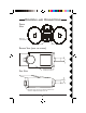
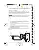
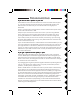
1. Connect a set of Audio/Video cables to the
A/V OUT jacks on the VR31A Video
Receiver. Connect the other end to your TV
(use Yellow for video, and either L or R
channel for audio). Note, VR36A receivers
do not have an audio output.
2. Plug the Video Receiver's Power Supply jack
into the Video Receiver and plug the power
supply into a 120 volt wall outlet.
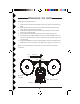
3. Turn the Video Receiver's power switch (on
side of unit) on.
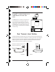
4. Set the channel switch to the same letter as you set on the camera, A, B, C,
or D.
5. Position the Video Receiver in a convenient location such as on top of the TV
and orient the antenna so that the flat side points in the direction where you
set up the Camera.
II
II
I
FF
FF
F
YY
YY
Y
OUROUR
OUROUR
OUR
TV TV
TV TV
TV
DOESDOES
DOESDOES
DOES
NONO
NONO
NO
TT
TT
T
HAHA
HAHA
HA
VEVE
VEVE
VE
A/V A/V
A/V A/V
A/V
CONNECTCONNECT
CONNECTCONNECT
CONNECT
ORSORS
ORSORS
ORS
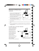
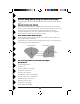
You can use a coaxial cable
(supplied with Model VR31A
receivers only) to connect
the TV OUT socket on the
VR31A Video Receiver to
the Antenna input on your
TV. If you already have an
antenna connected to your
TV, you will need to use a
TV antenna splitter.
Set your TV and the TV
Channel switch on the Video
Receiver (on bottom) to the
same channel (3 or 4).
Note model VR36A
receivers do not have a COAX output.