
User's Manual

44
44
4
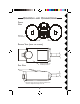
Whi te
Black
Whi te
Black
Whi te
Black
Blue
Whi te
White
Black
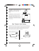
House Wiring
AA
AA
A
SSEMBLINGSSEMBLING
SSEMBLINGSSEMBLING
SSEMBLING
THETHE
THETHE
THE
PP
PP
P
ARTSARTS
ARTSARTS
ARTS
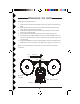
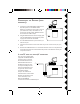
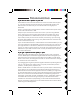
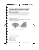
Referring to the diagram below:
1. Screw the base of each lamp holder into the outer holes on the mounting
plate.
2. Rotate the locking ring on each lamp holder towards the plate until the
lamp holder is secure against the plate.
3. Screw the threaded end of the motion activated camera into the center
hole on the mounting plate.
4. Lock the motion activated camera into place using the locking ring.
5. Locate each lamp holder's WHITE wire and one of the WHITE wires from
the motion activated camera and twist all three wires together using a wire
nut (supplied).
6. Locate each BLACK wire from the lamp holders and connect them both to
the BLUE wires from the motion activated camera, again using a wire nut.
Make sure no bare whiskers of wire stick out (cover with electrical tape if
necessary).
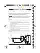
Bulbs not
included
Camera
Motion Sensor