Trademarks Autel®, MaxiSys®, MaxiDAS®, MaxiScan®, MaxiRecorder®, MaxiTPMS®, and MaxiCheck® are trademarks of Autel Intelligent Technology Corp., Ltd., registered in China, the United States and other countries. All other marks are trademarks or registered trademarks of their respective holders.
Safety Precautions and Warnings To prevent personal injury or damage to vehicles and/or the scan tool, read this instruction manual first and observe the following safety precautions at a minimum whenever working on a vehicle: Always perform automotive testing in a safe environment. Wear safety eye protection that meets ANSI standards. Keep clothing, hair, hands, tools, test equipment, etc. away from all moving or hot engine parts.
CONTENTS 1 GENERAL INFORMATION ..................................................................... 1 ON-BOARD DIAGNOSTICS (OBD) II .............................................................. 1 DIAGNOSTIC TROUBLE CODES (DTCS) ......................................................... 1 LOCATION OF THE DATA LINK CONNECTOR (DLC) .......................................... 2 OBD II READINESS MONITORS .................................................................... 3 OBD II MONITOR READINESS STATUS ......
DTC LOOKUP ......................................................................................... 36 5 ABSSRS TESTING ............................................................................... 38 ABSSRS DIAGNOSTIC TESTING .................................................................. 38 6 PRINT AND UPDATE ........................................................................... 44 PRINT ....................................................................................................
1 General Information On-Board Diagnostics (OBD) II The first generation of On-Board Diagnostics (called OBD I) was developed by the California Air Resources Board (ARB) and implemented in 1988 to monitor some of the emission control components on vehicles. As technology evolved and the desire to improve the On-Board Diagnostic system increased, a new generation of On-Board Diagnostic system was developed. This second generation of On-Board Diagnostic regulations is called "OBD II".
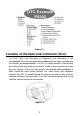
Figure 1-1 Location of the Data Link Connector (DLC) The DLC (Data Link Connector or Diagnostic Link Connector) is the standardized 16-cavity connector where diagnostic scan tools interface with the vehicle's on-board computer. The DLC is usually located 12 inches from the center of the instrument panel (dash), under or around the driver’s side for most vehicles. If Data Link Connector is not located under dashboard, a label should be there telling location.
OBD II Readiness Monitors An important part of a vehicle’s OBD II system is the Readiness Monitors, which are indicators used to find out if all of the emissions components have been evaluated by the OBD II system. They are running periodic tests on specific systems and components to ensure that they are performing within allowable limits. Currently, there are eleven OBD II Readiness Monitors (or I/M Monitors) defined by the U.S. Environmental Protection Agency (EPA).
The following monitors are to be used for compression ignition engines only: 1) EGR System 2) NMHC Catalyst 3) NOx Aftertreatment 4) Boost Pressure System 5) Exhaust Gas Sensor 6) PM Filter OBD II Monitor Readiness Status OBD II systems must indicate whether or not the vehicle’s PCM’s monitor system has completed testing on each component. Components that have been tested will be reported as “Ready”, or “Complete”, meaning they have been tested by the OBD II system.
OBD II Definitions Powertrain Control Module (PCM) – OBD II terminology for the on-board computer that controls engine and drive train. Malfunction Indicator Light (MIL) – Malfunction Indicator Light (Service Engine Soon, Check Engine) is a term used for the light on the instrument panel. It is to alert the driver and/or the repair technician that there is a problem with one or more of vehicle's systems and may cause emissions to exceed federal standards.
parameters such as engine RPM, vehicle speed, air flow, engine load, fuel pressure, fuel trim value, engine coolant temperature, ignition timing advance, or closed loop status. OBD II Modes of Operation Here is a basic introduction to the OBD II communication protocol. Mode byte: The first byte in the stream is the mode number. There are 9 modes for diagnostic requests, so this first byte is from 1 to 9. The first byte in the response data bytes is this same number plus 64.
4. $04 High sensor voltage threshold for switch time measurement 5. $05 Rich-to-Lean switch time in ms 6. $06 Lean-to Rich switch time in ms 7. $07 Minimum voltage for test 8. $08 Maximum voltage for test 9. $09 Time between voltage transitions in ms Mode $06 – Non-Continuously Monitored Systems test results. There are typically a minimum value, a maximum value, and a current value for each non-continuous monitor. This data is optional, and it is defined by a given vehicle make if it’s used.
2 Using the Scan Tool Tool Description Figure 2-1 1) OBD II CONNECTOR – connects the scan tool to the vehicle’s Data Link Connector (DLC). 2) LCD DISPLAY – indicates test results. 3) FUNCTION BUTTONS – corresponds with “buttons” on screen for executing commands.
4) ESC BUTTON – cancels a selection (or an action) from a menu or returns to the previous screen. 5) LEFT SCROLL BUTTON – when looking up DTC definitions, press to review previous character and to display additional information on previous screens if present; press to view previous screen or previous frames of recorded data. It is also used to view previous trouble code when viewing DTCs. 6) HELP BUTTON – displays help information and accesses DTC Guide function.
Accessories Included 1) User Manual – instructions on tool operations. 2) Quick Guide – instructions on registering tool and updating software. 3) OBDII Cable – used to connect tool to vehicle for communication and to power tool. 4) USB Cable – used to print retrieved data. 5) Protective Nylon Case – used to store the tool when not in use. 6) TF Card – used to store data and to upgrade the scan tool. Keyboard No solvents such as alcohol are allowed to clean the keypad or display.
System Setup The System Setup functions allow you to adjust default settings and view information about the scan tool. 1) Language: Selects the desired language. 2) Unit of Measure: Sets the unit of measure to English or Metric. 3) Beep Set: Turns on/off beep. 4) Key Test: Checks if the keyboard is working properly. 5) LCD Test: Checks if the LCD display is working properly. 6) About: Provides information of the scan tool. Tool operates with default settings until changed.
Figure 2-4 Unit of Measure Metric is the default measurement unit. 1) From System Setup screen, use the LEFT/RIGHT scroll button to select EN/METRIC and press the OK button. 2) From Unit of Measure screen, use the LEFT/RIGHT scroll button to select the desired unit of measurement. 3) Press the OK button to save your selection and return to previous menu. Or, press the ESC button to exit without saving. Figure 2-5 Beep Set The default setting is Beep On.
Figure 2-6 3) Press the OK button to save your selection and return to previous menu. Or, press the ESC button to exit without saving. Key Test The Key Test function checks if the keyboard is working properly. 1) From System Setup screen, use the UP/DOWN scroll button and LEFT/RIGHT scroll button to select Key Test, and press the OK button. 2) Press any key to start test. When you press a key, the edge around corresponding key on the screen should turn to red.
1) From System Setup screen, use the UP/DOWN scroll button and LEFT/RIGHT scroll button to select LCD Test, and press the OK button. 2) Look for missing spots in the red, green, blue, black and white LCD display. 3) When completed, press the ESC button to exit. About The About function displays important tool information including serial number and software version number.
Government regulations mandate that all OBD II compliant vehicles must have a “common” sixteen-pin Data Link Connector (DLC). For your vehicle to be OBD II compliant it must have a 16-pin DLC (Data Link Connector) under the dash and the Vehicle Emission Control Information Label must state that the vehicle is OBD II compliant.
Reset the scan tool. Turn the ignition off and wait for about 10 seconds. Turn the ignition back to on and continue the testing. Scan tool doesn’t power up If the scan tool won’t power up or operates incorrectly, do the following: Check if the scan tool’s OBD II connector is securely connected to the vehicle’s DLC; Check if the DLC pins are bent or broken. Clean the DLC pins if necessary. Check vehicle battery to make sure it is still good with at least 8.0 volts.
3 Playback Data The Playback Data function allows viewing and printing data from last recorded test. Review Data 1) Use the LEFT/RIGHT scroll button to select Playback from Main Screen, and press the OK button. Wait for the Review Data screen to appear. 2) To review data saved in the scan function, select Scan in the Replay menu. To review data saved in the AbsSrs function, select AbsSrs in the Replay menu. Then press OK button to continue.
4 OBDII Diagnostics The OBD II Diagnostics function is a fast-access option that allows you to carry out a quick test on the engine system of OBD II vehicles. When more than one vehicle control module is detected by the scan tool, you will be prompted to select the module with retrievable data. The Power train Control Module [PCM] and Transmission Control Module [TCM] are the most commonly scanned modules. CAUTION: Don’t connect or disconnect the scan tool while the ignition is on or the engine running.
Figure 4-1 If more than one module is detected, you will be prompted to select a module to test. Use the UP/DOWN scroll button to select a module and press the OK button. Read Codes The Read Codes function can be performed with the key on, engine off (KOEO) or with the key on, engine running (KOER).
Figure 4-2 2) Use the UP/DOWN scroll button to select Stored Codes, Pending Codes or Permanent Codes from the Read Codes menu and press the OK button. If no codes are found, a message will display “No (pending) codes are stored in the module!” Wait a moment or press any key to return to previous screen. NOTE Permanent Codes function is available only for vehicles supporting the CAN protocols. 3) View DTCs and their definitions on screen.
If the manufacturer of your vehicle is not listed, use the UP/DOWN scroll button to select Other and press the OK button. Erase Codes NOTE 1) Erasing the Diagnostic Trouble Codes may allow the scan tool to delete not only the codes from the vehicle’s on-board computer, but also “Freeze Frame” data and manufacturer-specific enhanced data. Further, the I/M Readiness Monitor Status for all vehicle monitors is reset to Not Ready or Not Complete status.
View Data The View Data function allows viewing of live or real time PID data of vehicle’s computer module(s). 1) To view live data, use the UP/DOWN scroll button to select Live Data from Diagnostic Menu and press the OK button. 2) Wait a few seconds while the scan tool validates the PID MAP. View Complete List 1) To view complete set of data, use UP/DOWN scroll button to select Complete List from Live Data menu and press the OK button. 2) View live PIDs on the screen.
Figure 4-6 If the Merge Graph on the bottom displays when a PID is selected to view, merged graph information is available. NOTE Merge Graph can be used to compare two related parameters in graphic mode, which is especially convenient in the Custom List option where you could select two interacted parameter to merge and see their relationship. Figure 4-7 Select Text to return to text viewing of PID data. Select Save to record retrieved live data and PID graphs.
Figure 4-8 The number to the right of selected item indicates sequence of this item. If you want to deselect the item, press Clear button. To select all the items on the screen, press Select All button. To clear all the selected items on the screen, press Clear All button. 3) Press the OK button to view selected PIDs on screen. 4) Use the ESC button to return to previous menu.
Figure 4-9 If you record live data under graph mode, following screen displays. Figure 4-10 NOTE The scan tool can only playback text data even though the data is saved in graphic mode. 2) When there is not enough memory space, a warning message prompting to delete previously recorded data. Figure 4-11 Select OK to return to the previous menu.
3) Select Pause to suspend recording. You could resume the recording process again by selecting Start. 4) You may review the saved data in Playback function. 5) Press ESC button to exit. Freeze Frame Data Freeze Frame Data allows the technician to view the vehicle’s operating parameters at the moment a DTC (Diagnostic Trouble Code) is detected. For example, the parameters may include engine speed (RPM), engine coolant temperature (ECT), or vehicle speed sensor (VSS).
Retrieve I/M Readiness Status I/M Readiness function is used to check the operations of the Emission System on OBD2 compliant vehicles. It is an excellent function to use prior to having a vehicle inspected for state emissions compliance. CAUTION: By clearing trouble codes you also clear the readiness status for the individual emission system readiness tests. In order to reset these monitors, the vehicle must be driven through a complete drive cycle with no trouble codes in memory.
Figure 4-13 4) Use the UP/DOWN scroll button to view the status of the MIL light (ON or OFF) and the following monitors.
Figure 4-14 5) If the vehicle supports readiness test of “This Drive Cycle”, a screen of the following displays. Figure 4-15 6) Use the UP/DOWN scroll button for more PIDs if additional information is available on more than one page. Or use the LEFT/RIGHT scroll button to view PIDs in the previous/next page. 7) Press the ESC button to return to Diagnostic Menu.
The O2 Monitor Test function is not supported by vehicles that communicate using a controller area network (CAN). For O2 Monitor Test results of CAN-equipped vehicles, see On-Board Monitor Test on page 30. 1) Use the UP/DOWN scroll button to select O2 Monitor Test from Diagnostic Menu and press OK button. 2) Wait while the scan tool validates the PID MAP. 3) Use the UP/DOWN scroll button to select O2 sensor from O2 Monitor Test menu and press OK button.
emission-related power train components and systems that are not continuously monitored. The On-Board Monitor Test for CAN-equipped vehicles retrieves and displays test results for emission-related power train components and systems that are and are not continuously monitored. The scan tool allows access to the results of on-board diagnostic monitoring tests for specific components/systems.
If the vehicle being tested does not support the mode, an advisory message will display on the screen. For CAN-equipped vehicles, test selections can be as depicted below. Figure 4-19 6) Use the UP/DOWN scroll button to select the desired monitor from On-Board Mon. Test menu and press the OK button. 7) View test data on screen. Figure 4-20 NOTE If the On-Board Monitor Test fails, this monitor item will be listed in red.
8) Press ESC button to return to the previous menu. Component Test The Component Test function initiates a leak test for the vehicle's EVAP system. The scan tool itself does not perform the leak test, but commands the vehicle's on-board computer to start the test. Different vehicle manufacturers might use different criteria and methods for stopping the test once it has been started. Before starting the Component Test, refer to the vehicle service manual for instructions to stop the test.
Figure 4-24 4) Wait a few seconds or press any key to return to previous screen. View Vehicle Information The Vehicle Info. function enables retrieval of Vehicle Identification No. (VIN), Calibration ID Nos. (CINs), Calibration Verification Nos. (CVNs) and In-use Performance Tracking on 2000 and newer vehicles that support Mode 9. 1) Use UP/DOWN scroll button to select Vehicle Info. from the Diagnostic Menu and press OK button.
5) Figure 4-26 View retrieved vehicle information on screen. 6) Figure 4-27 Press the ESC button to return to previous menu. Modules Present The Modules Present function displays the module communication protocols for OBD II modules in the vehicle. IDs and 1) Use the UP/DOWN scroll button to select Modules Present from Diagnostic Menu and press OK button. 2) View modules present with their IDs and communication protocols.
3) Press the ESC button to return to previous menu. DTC Lookup The DTC Lookup function provides descriptions of DTCs and helpful tips to resolve DTCs. It is useful for technicians to find the root cause of trouble code faster resulting in reduced diagnosis and repair time. 1) Use the UP/DOWN scroll button to select DTC Lookup from Diagnostic Menu and press OK button. 2) Wait for the scan tool to display the DTC Lookup screen. Figure 4-29 3) Select Show and a soft keyboard will pop up.
Figure 4-31 6) Use the LEFT/RIGHT scroll button to view the previous / next DTC. Select Save to record code definition. For manufacturer specific codes, you need to select a vehicle make on an additional screen to look for DTC definitions. If definition could not be found (SAE or Manufacturer Specific), the scan tool displays “Please refer to vehicle service manual!” For DTC Guide information, press ? Help button. Press No or ESC button to return to previous menu.
5 AbsSrs Testing ABS – Anti-lock Braking System in most vehicles is made up of an electronic hydraulic pump of two, three or most commonly four Wheel Speed Sensors (WSS), a G-force sensor, a Vehicle Speed Sensor and an ABS Control Module (EBCM). The EBCM is constantly monitoring the WSS, the Vehicle Speed Sensor, and the G-sensor. Diagnosing an ABS problem should always start with a visual inspection of all brake components, then you will need to retrieve ABS DTCs to tell you where the problem is.
2) Turn on the scan tool and wait for the Main Screen to appear. 3) Select AbsSrs icon in the Main Screen. 4) Select a specific vehicle manufacture’s regional coverage. Figure 5-1 5) From the vehicle make screen, select a specific vehicle manufacture and press OK button.
NOTE You may not need to make all the selections, or have to select other features. For some vehicles, the tool will not ask for any information before turning to the Function menu. 6) Use the UP/DOWN scroll button to select the desired control module from the retrieved engine data menu (in GM’s case, the selected engine model: 3.6 L (LFX)), and press the OK button.
7) A screen message will prompt up to inquire the accuracy of the Vehicle Specification, if the information is correct select the Yes option to continue, otherwise select the No option on the screen to exit without saving. 8) Enter correct Vehicle Identification Number (VIN) in the INPUT DATA menu. Figure 5-3 [Finish]: After entering a new value, use this key to save the value to the VIN. [Show]: Press this key to pop up a soft keyboard to facilitate your input. [Esc]: Press this key to exit.
NOTE The data you input must be in the reasonable range, which is defined by the preset values in VIN. If you enter a data out of range, the tool will display a warning message. Figure 5-5 9) Follow screen instruction to save vehicle information in the Input Dialog Box and Vehicle Specification sections by selecting Yes option, or No option to exit without saving. Figure 5-6 10) Select a desired item for information on the option menu screen.
11) Select the Control Unit entry to enter the System Menu option screen, and choose the desired Control Module entry for DTC information stored in the vehicle’s on-board computer. Figure 5-8 If there is not any Diagnostic Trouble Code, the display indicates “No (pending) codes are stored in the module!” Wait a few seconds or press any key to return to previous screen. NOTE 1. In this manner, the scan tool will communicate with the vehicle being tested. If there is a linking error, please refer to 3.
6 Print and Update Print The Print Data function allows printing DTC data recorded by the tool by connecting the tool to a Windows-based PC with the supplied USB cable. 1. Download the Maxi PC Suite from www.autel.com > Support & Updates > Firmware & Downloads > Update Client, and install to your Windows-based computer. 2. Connect the tool to the computer using the supplied USB cable. 3. Run Autel Printer software on the computer. 4. Select Playback on the Main Screen of the tool.
Update To update your scan tool, you need the following items. MaxiLink ML619 A Windows-based computer or laptop with USB ports The provided USB cable Register the Tool The tool must be registered prior to updating it. Register the tool on our website: www.autel.com. Visit the site to download software update programs, research tools and retrieve warranty information. NOTE Prior to registration, please confirm your network is working properly. 1. Visit the website http://pro.autel.com. 2.
Follow the update procedure to finish updating. 1. Download the Maxi PC Suite from www.autel.com > Support & Updates > Firmware & Downloads > Update Client, and install to your Windows-based computer. 2. Run the Maxi PC Suite. Wait for the Log In window to display. Figure 6-2 Sample Log In Window 3. Enter your Autel ID and password and wait for the Update window to display. If you forget your password, click the [Forget Password?] link to our website and retrieve your password.
2. Or, click on the Select All checkbox on the bottom left of screen and all updatable items will be selected. Click the Update All button on the right of the screen. 3. When the download is completed, the programs will be automatically installed. The new version will replace the old version. Single Update 1. Locate the desired update and click the Update button in the same line. 2. The downloaded programs will automatically install. The update will replace the existing version of the software.
The deleted program(s) will be added to the end of the program list on the Update page to install again if you wish. In the search box on the top right corner of the screen, you can search the listed. This function works for both Update Available column and Installed column.
7 Compliance Information FCC COMPLIANCE This device complies with Industry Canada’s licence-exempt RSSs. Operation is subject to the following two conditions: 1. This device may not cause harmful interference. 2. This device must accept any interference received, including interference that may cause undesired operation. Cet appareil est conforme aux CNR exempts de licence d’Industrie Canada. Son fonctionnement est soumis aux deux conditions suivantes: 1.
– Connect the equipment into an outlet on a circuit different from that to which the receiver is connected. – Consult the dealer or an experienced radio/TV technician for help. Changes or modifications not expressly approved by the party responsible for compliance could void the user’s authority to operate the equipment. RF WARNING STATEMENT The device has been evaluated to meet general RF exposure requirement. The device can be used in portable exposure condition without restriction.
8 Warranty and Service Limited One Year Warranty Autel Intelligent Technology Corp., Ltd.
IMPORTANT All contents of the product may be deleted during the process of repair. You should create a back-up copy of any contents of your product before delivering the product for warranty service. Service and Support If you have any questions regarding the product, please contact one of our offices in your region. AUTEL NORTH AMERICA Phone: 855-AUTEL-US (855-288-3587) Mon.-Fri.9am-6pm EST Website: www.autel.com Email: ussupport@autel.
AUTEL AUSTRALIA Phone: 03 9480 2978 / +61 476293327 Website: www.autel.com.au Email: sales@autel.com.au Address: 155 Islington Street, Melbourne, Collingwood, VIC For technical assistance in other markets, please contact your local tool distributor.