Trademarks Autel®, MaxiSys®, MaxiDAS®, MaxiScan®, MaxiRecorder®, MaxiTPMS®, and MaxiCheck® are trademarks of Autel Intelligent Technology Corp., Ltd., registered in China, the United States and other countries. All other marks are trademarks or registered trademarks of their respective holders.
Safety Precautions and Warnings To prevent personal injury or damage to vehicles and/or the scan tool, read this instruction manual first and observe the following safety precautions at a minimum whenever working on a vehicle: Always perform automotive testing in a safe environment. Wear safety eye protection that meets ANSI standards. Keep clothing, hair, hands, tools, test equipment, etc. away from all moving or hot engine parts.
CONTENTS 1 GENERAL INFORMATION ..................................................................... 1 ON-BOARD DIAGNOSTICS (OBD) II .............................................................. 1 DIAGNOSTIC TROUBLE CODES (DTCS) ......................................................... 1 LOCATION OF THE DATA LINK CONNECTOR (DLC) .......................................... 2 OBD II READINESS MONITORS .................................................................... 3 OBD II MONITOR READINESS STATUS ......
6 WARRANTY AND SERVICE ................................................................. 40 LIMITED ONE YEAR W ARRANTY ................................................................. 40 SERVICE AND SUPPORT ............................................................................
1 General Information On-Board Diagnostics (OBD) II The first generation of On-Board Diagnostics (called OBD I) was developed by the California Air Resources Board (ARB) and implemented in 1988 to monitor some of the emission control components on vehicles. As technology evolved and the desire to improve the On-Board Diagnostic system increased, a new generation of On-Board Diagnostic system was developed. This second generation of On-Board Diagnostic regulations is called "OBD II".
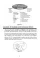
Figure 1-1 Location of the Data Link Connector (DLC) The DLC (Data Link Connector or Diagnostic Link Connector) is the standardized 16-cavity connector where diagnostic scan tools interface with the vehicle's on-board computer. The DLC is usually located 12 inches from the center of the instrument panel (dash), under or around the driver’s side for most vehicles. If Data Link Connector is not located under dashboard, a label should be there telling location.
OBD II Readiness Monitors An important part of a vehicle’s OBD II system is the Readiness Monitors, which are indicators used to find out if all of the emissions components have been evaluated by the OBD II system. They are running periodic tests on specific systems and components to ensure that they are performing within allowable limits. Currently, there are eleven OBD II Readiness Monitors (or I/M Monitors) defined by the U.S. Environmental Protection Agency (EPA).
The following monitors are to be used for compression ignition engines only: 1) EGR System 2) NMHC Catalyst 3) NOx Aftertreatment 4) Boost Pressure System 5) Exhaust Gas Sensor 6) PM Filter OBD II Monitor Readiness Status OBD II systems must indicate whether or not the vehicle’s PCM’s monitor system has completed testing on each component. Components that have been tested will be reported as “Ready”, or “Complete”, meaning they have been tested by the OBD II system.
OBD II Definitions Powertrain Control Module (PCM) – OBD II terminology for the on-board computer that controls engine and drive train. Malfunction Indicator Light (MIL) – Malfunction Indicator Light (Service Engine Soon, Check Engine) is a term used for the light on the instrument panel. It is to alert the driver and/or the repair technician that there is a problem with one or more of vehicle's systems and may cause emissions to exceed federal standards.
parameters such as engine RPM, vehicle speed, air flow, engine load, fuel pressure, fuel trim value, engine coolant temperature, ignition timing advance, or closed loop status. OBD II Modes of Operation Here is a basic introduction to the OBD II communication protocol. Mode byte: The first byte in the stream is the mode number. There are 9 modes for diagnostic requests, so this first byte is from 1 to 9. The first byte in the response data bytes is this same number plus 64.
4. $04 High sensor voltage threshold for switch time measurement 5. $05 Rich-to-Lean switch time in ms 6. $06 Lean-to Rich switch time in ms 7. $07 Minimum voltage for test 8. $08 Maximum voltage for test 9. $09 Time between voltage transitions in ms Mode $06 – Non-Continuously Monitored Systems test results. There are typically a minimum value, a maximum value, and a current value for each non-continuous monitor. This data is optional, and it is defined by a given vehicle make if it’s used.
2 Using the Scan Tool Tool Description Figure 2-1 1. OBD II CONNECTOR – connects the scan tool to the vehicle’s Data Link Connector (DLC). 2. LCD DISPLAY – displays test results. 3. GREEN LED – indicates that engine systems are running normally (The monitors on the vehicle are active and performing their diagnostic testing is in the allowed limit, and no DTCs are present).
4. YELLOW LED – indicates there is a possible problem. A “Pending” DTC is present and/or some of the vehicle’s emission monitors have not run their diagnostic testing. 5. RED LED – indicates there is a problem in one or more of the vehicle’s systems. The red LED also indicates DTCs are present. DTCs display the scan tool’s display. In this case, the MIL on the vehicle’s instrument panel will light steady. 6.
Keyboard No solvents such as alcohol are allowed to clean the keypad or display. Use a mild nonabrasive detergent and a soft cotton cloth. Do not soak the keypad as the keypad is not waterproof. Power The scan tool is powered via the vehicle Data Link Connector (DLC). Just follow the steps below to turn on the scan tool: 1) Locate DLC on vehicle. A plastic DLC cover may be found for some vehicles and you need to remove it before attaching the OBD II cable.
Figure 2-2 From the Main Screen: Use the SCROLL button to select Setup, and press the ENTER/Exit button. Follow the instructions to make adjustments and settings as described in the above setup options. Figure 2-3 Language Setup English is the default language. 1) From System Setup screen, use the SCROLL button to select Language, and press the ENTER/Exit button. 2) Use the SCROLL button to select the desired language and press ENTER/Exit to save your selection and return to previous screen.
Configure Monitors From System Setup screen, use the SCROLL button to select Configure Monitors, and press the ENTER/Exit button. Figure 2-5 On this menu, configure the number of monitors to pass diagnosis, and restore the default settings. 1) Allowed INC Monitors From Configure Monitors screen, use the SCROLL button to select Allowed INC Monitors, and press the ENTER/Exit button. Emissions tests vary depending on the geographic or regional area in which the vehicle is registered.
2) From Unit of Measure screen, use the SCROLL button to select the desired unit of measurement. Figure 2-6 3) Press the ENTER/Exit button to save your selection and return to previous menu. Key Beep Set This function allows you to turn on/off the build-in speaker for key pressing. The default setting is Beep On. 1) From System Setup screen, use the SCROLL button to select Key Beep Set and press the ENTER/Exit button.
This function allows you to turn on/off the built-in speaker as an indicator during diagnostic testing. Different audio tones correspond to different LED lights. This function is invaluable when performing diagnostics alone, or while working in bright areas where LED illumination alone is not sufficient. 1) From System Setup screen, use the SCROLL button to select Status Beep Set and press the ENTER/Exit button.
Figure 2-9 3) When completed, press the ENTER/Exit button to exit. B. Keyboard Test The Keyboard Test function verifies if the keys are functioning properly. 1) Use the SCROLL button to select Keyboard Test from the Tool Self-test menu, and then press the ENTER/Exit button. 2) Press any key to start test. When you press a key, the key name should display on screen. If the key name does not display, the key is not functioning. Figure 2-10 The [OK] button refers to ENTER/Exit button.
2) In the LED Self-test menu, use the SCROLL button to select one or more LED lamps to test. The LED should turn on or off according to the selected commands. Figure 2-11 3) When completed, select Previous Menu and press the ENTER/Exit button to exit. Update Mode To update your scan tool, you need the following items. MaxiLink ML319 A Windows-based computer or laptop with USB ports The provided USB cable Update Procedure Autel frequently releases software updates to download.
Figure 2-12 Sample Update Window To Exit the Setup Menu Use the SCROLL button to select Previous Menu from the System Setup screen, and press the ENTER/Exit button to return to Main Screen. About The About function displays important tool information including serial number and software version number. 1) From Main Screen, use the SCROLL button to select About and press the ENTER/Exit button; wait for the About screen to display. 2) View tool information on screen.
and European vehicles, 1996 and newer (including light trucks), sold in the United States must be OBD II compliant. A small number of 1994 and 1995 model year gasoline vehicles are OBD II compliant. To verify if a 1994 or 1995 vehicle is OBD II compliant, check the Vehicle Emissions Control Information (VECI) Label which is located under the hood or by the radiator of most vehicles. If the vehicle is OBD II compliant, the label will designate “OBD II Certified”.
Turn the ignition off and wait for about 10 seconds. Turn the ignition back to on and continue the testing. Scan Tool Doesn’t Power Up If the scan tool won’t power up or operates incorrectly, do the following: Check if the scan tool’s OBD II connector is securely connected to the vehicle’s DLC; Check if the DLC pins are bent or broken. Clean the DLC pins if necessary. Check vehicle battery to make sure it is still good with at least 8.0 volts.
3 OBD II Diagnostics When more than one vehicle control module is detected by the scan tool, you will be prompted to select the module with retrievable data. The Power train Control Module [PCM] and Transmission Control Module [TCM] are the most commonly scanned modules. CAUTION: Don’t connect or disconnect the scan tool while the ignition is on or the engine running. 1) Turn the ignition off. 2) Locate the vehicle’s 16-pin Data Link Connector (DLC). 3) Plug the tool into the vehicle’s DLC.
Figure 3-1 If more than one module is detected, you will be prompted to select a module to test. Figure 3-2 Use the SCROLL button to select a module and press the ENTER/Exit button to confirm. Read Codes The Read Codes function can be performed with the key on, engine off (KOEO) or with the key on, engine running (KOER).
indicator light (MIL). If the fault does not occur within a certain number of warm-up cycles, the code clears from memory. Permanent Codes are DTCs that are "confirmed" and are retained in the non-volatile memory of the vehicle’s computer until the appropriate monitor for each DTC has determined that the malfunction is no longer present and is not causing the MIL. Permanent DTCs are stored in non-volatile memory and can not be erased by any diagnostics service or by disconnecting power to ECU.
3) View DTCs and their definitions on screen. Press ENTER/Exit button to return to previous screen. Figure 3-5 4) The control module number, sequence of the DTCs, total number of codes detected and type of codes (Generic or Manufacturer specific, Stored or Pending codes) will be observed on the upper right hand corner of the display. If more than one DTC is found, use the SCROLL button to review each code.
5) Select Previous Menu from the Read Codes screen, and press ENTER/Exit button to return to previous menu. Erase Codes NOTE 1. Erasing the Diagnostic Trouble Codes may allow the scan tool to delete not only the codes from the vehicle’s on-board computer, but also “Freeze Frame” data and manufacturer-specific enhanced data. Further, the I/M Readiness Monitor Status for all vehicle monitors is reset to Not Ready or Not Complete status. Do not erase the codes before repairs or services have been performed.
Figure 3-8 If the codes are not cleared, then an “Erase Failure. Turn Key on with Engine off!” message displays. Live Data The function allows viewing of live or real time PID data of vehicle’s computer module(s). 1) To view live data, use the SCROLL button to select Live Data from Diagnostic Menu and press the ENTER/Exit button. 2) Wait a few seconds while the scan tool validates the PID MAP.
Figure 3-10 4) View live PIDs on the screen. Use the SCROLL button for more PIDs if additional information is available on more than one page. Figure 3-11 The number “x” to the right of the screen indicates the sequence of the highlighted item. 5) Press the ENTER/Exit button to return to previous menu. 6) Select Previous Menu from the Read Codes screen, and press ENTER/Exit button to return to previous menu.
2) Wait while the scan tool validates the PID MAP. 3) If retrieved information displays on more than one screen, use the SCROLL button, as necessary, until all the data have shown up. Figure 3-12 4) If no freeze frame data is available, the message “No freeze frame data stored displays. Press ENTER/Exit button to return to previous screen. Retrieve I/M Readiness Status I/M Readiness function is used to check the operations of the Emission System on OBD II compliant vehicles.
INC – indicates that a particular monitor being checked has not completed its diagnostic testing. N/A – the monitor is not supported on that vehicle. There are two ways to retrieve I/M readiness status. Retrieve I/M Readiness Status with One-Click I/M Readiness Key Press the One-Click I/M Readiness Key, to retrieve I/M readiness status. The screen will display as below. The LEDs colors and the audio tones indicate readiness status.
YELLOW LED – with MIL off, there may be three possible conditions to cause the yellow LED to light. If a “Stored” Diagnostic Trouble Code is causing the yellow LED to light, it is still possible that the vehicle will be allowed to be tested for emissions and certified. If a “Pending” Diagnostic Trouble Code is causing the yellow LED to light, it is still possible that the vehicle will be allowed to be tested for emissions and certified.
Yellow LED short, long, short beep 5 seconds Red LED Four short beeps 5 seconds After you have read the information, press ENTER/Exit to exit. The other buttons are disabled to prevent misoperation. Retrieve I/M Readiness Status in Typical Way 1) Use the SCROLL button to select I/M Readiness from Diagnostic Menu and press ENTER/Exit button. 2) Wait while the scan tool validates the PID MAP.
For compression ignition engines: MIS – Misfire Monitor FUEL – Fuel System Monitor CCM – Comprehensive Component Monitor EGR – EGR System Monitor HCCAT – NMHC Catalyst Monitor NCAT – NOx Aftertreatment Monitor BP – Boost Pressure System Monitor EGS – Exhaust Gas Sensor Monitor PM – PM Filter Monitor Figure 3-15 1) If the vehicle supports readiness test of “This Drive Cycle”, a screen of the following displays: Figure 3-16 2) The LEDs and audio tones corresponding to di
Yellow LED short, long, short beep 2 minutes Red LED Four short beeps 2 minutes 3) Use the SCROLL button for more PIDs if additional information is available on more than one page. 4) Press the ENTER/Exit button to return to Diagnostic Menu. View Vehicle Information The Vehicle Info. function enables retrieval of Vehicle Identification No. (VIN), Calibration ID Nos. (CINs), Calibration Verification Nos. (CVNs) and In-use Performance Tracking on 2000 and newer vehicles that support Mode 9.
If the vehicle does not support this mode, a message displays that the mode is not supported. 4) From Vehicle Info. menu, use the SCROLL button to select an available item to view and press the ENTER/Exit button. 5) View retrieved vehicle information on screen. Figure 3-19 Figure 3-20 6) Select Previous Menu from the Vehicle Info screen, and press ENTER/Exit button to return to the previous menu.
4 Ready Test This function can be used as a convenient readiness test tool by automotive technicians to determine if the tested vehicle is ready for an emission test. By visual and audible indication, you will learn a vehicle’s emissions readiness. General Information Repairs to the emissions-control systems of a 1996 or newer vehicle cause the vehicle’s computer (ECU) memory to be cleared.
Use the SCROLL button to select Ready Test from Main Screen, and press the ENTER/Exit button. Figure 4-1 As Post-Repair Diagnostic Tool This function can be used (after the vehicle has done any emission-related repairs) to confirm that the repair has been performed successfully. After repairs, some drive cycles are required to reset the monitoring systems. Drive cycles vary by vehicle and by monitor.
color LEDs and audible tone if your vehicle is ready to conduct state emission test. 2) If the GREEN LED lights and two long beeps are heard, your vehicle is ready and it should pass emissions testing. 3) If the RED LED lights, your vehicle is not ready and must be repaired before an emission test can be performed. NOTE 1. If you are driving the vehicle to perform a drive cycle ALONE, set the Status Beep On. The beep signifies that the monitors have run and the diagnostics testing completed.
If the scan tool is idle, the result will immediately display. If it is busy, it will wait till the current procedure finished. After viewing the status, press ENTER/Exit button to exit. OK – indicates that a particular monitor being checked has completed its diagnostic testing. INC – indicates that a particular monitor being checked has not completed its diagnostic testing. N/A – the monitor is not supported on that vehicle.
5 Compliance Information FCC COMPLIANCE This device complies with Industry Canada’s licence-exempt RSSs. Operation is subject to the following two conditions: 1. This device may not cause harmful interference. 2. This device must accept any interference received, including interference that may cause undesired operation. Cet appareil est conforme aux CNR exempts de licence d’Industrie Canada. Son fonctionnement est soumis aux deux conditions suivantes: 1.
– Reorient or relocate the receiving antenna. – Increase the separation between the equipment and receiver. – Connect the equipment into an outlet on a circuit different from that to which the receiver is connected. – Consult the dealer or an experienced radio/TV technician for help. Changes or modifications not expressly approved by the party responsible for compliance could void the user’s authority to operate the equipment.
6 Warranty and Service Limited One Year Warranty Autel Intelligent Technology Corp., Ltd.
Service and Support If you have any questions regarding the product, please contact one of our offices or your local distributor. AUTEL NORTH AMERICA Phone: 855-AUTEL-US (855-288-3587) Mon.-Fri. 9am-6pm EST Website: www.autel.com Email: ussupport@autel.com Address: 175 Central Avenue, Suite 200, Farmingdale, New York, USA. 11735 AUTEL EUROPE Phone: 0049 (0) 61032000522 Website: www.autel.eu Email: sales.eu@autel.com, support.eu@autel.