Table of Contents 1. 2. 3. 4. 5. 6. Safety Instructions............................................................................. 1 1.1 Work Area Safety .................................................................... 1 1.2 Electrical Safety ....................................................................... 1 1.3 Personal Safety ........................................................................ 2 Description, Specifications and Tool Components.......................... 3 2.
Safety Instructions 1. Safety Instructions IMPORTANT: To prevent electric shock, fire and/or personal injury or damage, read this user’s manual first and observe the following safety instructions. 1.1 Work Area Safety Always perform automotive testing in a safe environment. Keep your work area clean and well lit. Cluttered benches and dark areas may cause accidents. Keep clothing, hair, hands, tools, test equipment, etc. away from all moving or hot engine parts.
Safety Instructions 1.3 Personal Safety Do not use the tool while tired or under the influence of drugs, alcohol, or medications. A moment of interruption can result in serious personal injury. Do not over-reach. Keep proper footing and balance at all times. Proper footing and balance enables better control of the tool in unexpected situations. Always wear safety eye protection that meets ANSI standards. Do not wear loose clothing or jewelry.
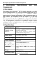
Description, Specification and Tool Components 2. Description, Components Specifications and Tool 2.1Description This premier Autel MaxiVideoTM MV208 digital videoscope is an ideal tool for examining difficult- to- reach areas normally hidden from sight. It features the ability to record digital still images and MPEG2 or MPEG1 videos either on its internal flash memory or on the removable Micro SD card (Optional). The ergonomic tool not only features a 2.
Description, Specification and Tool Components Image controls Zoom, low light vision Lighting Fully adjustable LED Cable reach 1m (3') -- expandable to 6m (19') w/optional extensions 8.5mm (0.33") is standard and 5.5mm (0.22") is optional. Imager head 1 Waterproof Imager head and cable to 3m (10') Additional ports USB, video out (TV-out) port Operating temp. Main unit: 32°F to 113°F (0°C to 45°C); Cable: 14°F to 176°F (-10°C to 80°C) Storage temp.
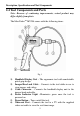
Description, Specification and Tool Components 2.4 Tool Components and Ports Note: Because of continuing improvements, actual product may differ slightly from photo. 1 The MaxiVideoTM MV208 comes with the following items: Fig. 1 1) 2) 3) 4) 5) 6) Handheld Display Unit – The ergonomic tool with comfortable pistol grip design. Imager Head and Cable – Connects to the tool while in use to view images and videos. Cable Connector – Connects the handheld display unit to the imager head and cable.
Description, Specification and Tool Components 7) 8) 9) Mini USB Port – Connects the tool to a computer with the supplied USB cable to exchange information. Micro SD card Slot – Holds the Micro SD card. Battery Compartment Cap- Indicates to install or remove the battery. Fig. 2 10) Accessory Magnet – Picks up small metal objects such as dropped rings or screws on the floor. 11) Accessory Hook – Unclogs obstacles and picks up wires in the pipes or confined areas.
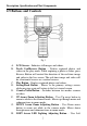
Description, Specification and Tool Components 2.5 Buttons and Controls Fig. 3 A. LCD Screen – Indicates still images and videos. B. Trash Can/Reverse Button – Deletes captured photos and videos in the play mode. While capturing a photo or video, press Reverse Button will control the direction of the real-time image and video in the live screen. The real-time image and video will do a horizontal reverse or a vertical reverse. C. Play Button – Replays captured photos and videos. D.
Description, Specification and Tool Components I. J. arrow button to decrease LED brightness in the camera mode. Moves the cursor to the desired item. Moves to the previous image or video in the play mode. RIGHT Arrow LED Lighting Adjusting Button – Uses Right arrow button to increase LED brightness in the camera mode. Moves the cursor to the desired item. Moves to the next image or video in the play mode. OK Button – Confirms a selection (or action) from a menu.
Installation and Connection 3. Installation and Connection 3.1 Battery Removal and Installation Note: If the power indicator light is blinking continuously, this reminds you to replace batteries in time as instructed. Fig. 4 1) Turn the display unit handheld upside down to expose the battery compartment cap and screw. (Fig. 4) 2) Use a screwdriver to remove screw and battery compartment cap. 3) Battery removal and installation. Fig.
Installation and Connection 4) Proper battery orientation is indicated in the battery compartment. 5) Replace the battery compartment and screw using a screwdriver to close the battery compartment cap. 3.2 Battery Precautions Remove the battery while cleaning the tool. Remove the battery before storing the tool for a long period of time to prevent battery leakage from damaging battery compartment. When necessary, replace all four (4) batteries with new ones.
Installation and Connection Fig. 7 Slip the end of the accessory over the tip of the imager head to fix the accessory as shown in Fig. 8. Fig. 8 3.5 Micro SD card Installation NOTE: Micro SD card slot provides for additional memory, but Micro SD card is optional and not included. Different Micro SD cards can be used to insert into the Micro SD card slot. The maximum 16 GB of the Micro SD card can be supported.
Installation and Connection 3.6 USB Cable Connection Use the supplied USB cable to connect the tool to a PC to upload and view captured photos and videos. A “USB Connected” message will appear on the screen as shown. (Fig.9) Fig. 9 3.7 Video-Out (TV-out) Cable Connection Insert the video-out cable into the video-out port of the tool and the other end of the cable into the video-in port of a TV, the LCD screen will output a high quality real-time image.
Operation Instruction 4. Operation Instructions IMPORTANT: Always wear safety eye protection to protect your eyes against dirt and other objects. Follow operation instructions to reduce the risk of injury from electric shock, entanglement and other causes. 1 4.1 Basic Operation NOTE: When in operation, the cable can be bent into a certain shape. This may help you operate the cable into confined areas. 1) Hold the tool with LCD screen facing you and press Power button to turn it on.
Operation Instruction TV to view a high quality real-time image. 4.2 Operation Precautions Use the tool only as directed. Do not operate the tool unless the user’s manual has been read thoroughly and proper training has been completed. The display unit is not waterproof. The imager head and cable are waterproof, but not acid-proof or fireproof.
Operation Instruction manufacturer for the tool. Always use appropriate personal protective equipment while handling and using the tool. Appropriate personal protective equipment always includes safety glasses and gloves, and may include latex or rubber gloves, face shields, goggles, protective clothing, respirators and steel toed footwear. Protect against excessive heat. The tool should be kept away from heat sources such as radiators, stoves or others that produce heat.
Operation Instruction the tool checked by a qualified technician. Any tool that cannot be controlled with the power button is dangerous and must be repaired. NOTE: Please check following methods to avoid injury. 2 FOR WALLS: For inspecting the inside walls, be sure to shut off the circuit breaker to the whole house before using the tool. FOR PIPES: If you suspect a metal pipe could contain an electric charge, have a qualified electrician to check the pipe before using.
Operation Instruction 3) 4) Check if any chemicals are present, especially in the case of drains. Chemicals may damage the tool. Check the temperature of the area. The working temperature of the tool is between 32°F (0°C) and 113°F (45°C). Check if any moving parts are present in the area. Make sure the tool has been properly inspected. Install the correct accessories for use in the appropriate application. CAUTION: Make sure the tool has been powered off before performing maintenance.
Operation Instruction referred to as the splash screen. (Fig. 10) This screen tells you the tool is booting up. Once the tool is fully powered up, the screen will automatically switch to the live screen. Fig. 10 2) Live Screen The live screen is where you will do most of your work. A live image of what the imager head sees is displayed on the screen. You can zoom, adjust screen backlighting, rotate images and videos, view and capture photos and videos from this screen.
Operation Instruction 5) Zooming Simply press UP and DOWN arrow buttons while in the still camera mode to zoom in or out. A zoom indicator bar will be displayed on the screen as you adjust zoom. (Fig. 12) Fig. 12 6) Entering the Primary Settings Screen Pressing Setting button while in the live screen will take you to the primary settings screen. (Fig. 13) Pressing Back button at any point will take you back to the live screen. Fig.
Operation Instruction Fig.14 Use the LEFT/RIGHT button to move to the desired option, then press OK button to save configuration and exit, or press Back button to exit without saving changes. Format Media In the Setup screen, select Format Media and press OK button, then the Format Media setting screen will appear. (Fig. 15) Fig.15 If you want to format the media (in most cases, it is the Micro SD card), use the LEFT/RIGHT button to select Yes, then press OK button to begin formatting.
Operation Instruction Help This function provides the firmware version information. In the Setup screen, select Help and press OK button, then the firmware version screen will appear. (Fig. 16) Fig.16 7) Entering the Secondary Settings Screen While in the Primary Settings Screen (Fig. 13), select Advanced Settings from Setup and then press OK button, you will enter the secondary settings screen (Fig. 17) where you can set Date and Time, Language and TV-out as needed.
Operation Instruction Fig.18 Use the LEFT/RIGHT button to move to the desired dialog box, then use the UP/DOWN button to increase or decrease the number. When finished, press OK button to save configuration and exit, or press Back button to exit without saving changes. Language In the Advanced Settings screen, select Language and press OK button, then the Language setting screen will appear. (Fig. 19) English is the default language. Fig.
Operation Instruction Fig. 20 Use the UP/DOWN button to select the desired setting, then press OK button to save configuration and exit, or press Back button to exit without saving changes. 8) Capturing a Photo When in the live screen, make sure the camera icon is present at the top left portion of the screen. (Fig. 21) Press OK button to capture a photo and simultaneously the photo has been saved to internal memory or the Micro SD card if available. Fig.
Operation Instruction capacity icon. This shows that video is capturing. The time at the top left portion, just below video icon, will begin counting. This indicates how long the video has been captured. Press OK button again to stop capturing a video. Fig. 22 It may take few seconds to save the captured video to internal memory. The tool could capture a video approximately 80s without a Micro SD card.
Operation Instruction Fig. 24 While viewing these photos and videos, press OK button to select, and then the screen will display as below (Fig.25). The digit on the top left portion of the screen shows sequence number of the playing file and total number of files in the folder. Fig.25 Use the LEFT button to play the previous file, the RIGHT button to the next file. Or, use the UP button to play the file on the previous line, the DOWN button to the file on the next line.
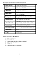
Operation Instruction Fig. 26 Select Yes to confirm your selection and press OK button to delete the file, or select No to cancel the command and press OK button to exit. NOTE: Files or videos only can be deleted one by one! When you delete all the photos or videos, a “No Files Available” message appears on the screen. (Fig. 27) Fig. 27 4.6 Icons 1) Battery Capacity – Fully charged battery. 2) Micro SD card – Indicates a Micro SD card has been inserted into the tool.
Operation Instruction 4) Video Camera – Indicates the tool is operating in video camera mode. 4.7 Software Update NOTE: The tool supports software update when there is new progress with software or system. We offer free update file for the tool. 1) Format your Micro SD card to FAT file format on a computer. 2) Visit our website www.auteltech.com and download software update file to your Micro SD card. 3) Insert your Micro SD card into the Micro SD card slot. (See 3.
Troubleshooting 5. Troubleshooting SYMPTOMS Display is on, but does not show image. POSSIBLE REASONS Cable connection is loose. Imager head is covered by debris. SOLUTIONS Check and reattach. Check if it is covered by debris. LED on imager head are dim at max brightness, display changes between monochrome, color display turns itself OFF after a short period. Low battery. Charge battery. The tool will not turn on. Dead battery. Replace battery.
Warranty Information 6. Warranty Information 6.1 Limited One Year Warranty Autel warrants to its customers that this product will be free from all defects in materials and workmanship for a period of one (1) year from the date of the original purchase, subject to the following terms and conditions: 1) The sole responsibility of Autel under the Warranty is limited to either the repair or, at the option of Autel, replacement of the tool at no charge with Proof of Purchase.