Table of Contents 1. SAFETY PRECAUTIONS AND WARNINGS .............................................. 1 2. GENERAL INFORMATION .......................................................................... 2 2.1 ON-BOARD DIAGNOSTICS (OBD) II ............................................................. 2 2.2 OIL/SERVICE RESET ..................................................................................... 2 2.3 EPB.......................................................................................
5.10. MODULES PRESENT .................................................................................... 42 5.11. DTC LOOKUP ............................................................................................. 43 6. TPMS (TIRE PRESSURE MONITOR SYSTEM) ...................................... 45 6.1. ENTER THE VEHICLE INFORMATION ........................................................... 45 6.2. TPMS DIAGNOSTICS ...................................................................................
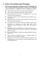
1. Safety Precautions and Warnings To prevent personal injury or damage to vehicles and/or the scan tool, read this instruction manual first and observe the following safety precautions at a minimum whenever working on a vehicle: Always perform automotive testing in a safe environment. Wear safety eye protection that meets ANSI standards. Keep clothing, hair, hands, tools, test equipment, etc. away from all moving or hot engine parts.
2. General Information 2.1 On-Board Diagnostics (OBD) II The first generation of On-Board Diagnostics (called OBD I) was developed by the California Air Resources Board (ARB) and implemented in 1988 to monitor some of the emission control components on vehicles. As technology evolved and the desire to improve the On-Board Diagnostic system increased, a new generation of On-Board Diagnostic system was developed. This second generation of On-Board Diagnostic regulations is called "OBD II".
The EPB is a system which controls the brake force by pulling the parking cable as in conventional existing parking brakes. EPB system includes a DC motor, a gearbox, a screw, a nut, a current sensor, a Hall-effect force sensor, an acceleration sensor and an ECU. Generally, if a driver or a high level system operates the EPB system, the controller calculates a target force from the parking cable based on the car mass as well as the inclination of the road as measured by the acceleration sensor.
constantly monitoring the WSS, the Vehicle Speed Sensor, and the G-sensor. Diagnosing an ABS problem should always start with a visual inspection of all brake components, then you will need to retrieve ABS DTCs to tell you where the problem is. SRS - “Supplemental Restraint System” is made up of Impact Sensors, a Control Module, and Airbags.
Self-Calibration Some newer vehicles can auto calibrate by having the wheel turned from lock to lock and then centered and cycling the key。 Scan Tool Steering Angle Sensor Reset There are many options for scan tools to reset SASs. Some tools are even integrated into an alignment system. But, most tools recommend that the calibration be performed on a level surface. Also, it is a good idea to perform a lock-to-lock turn to complete the calibration. 2.
Regeneration is the DPF‘s way to clear the blockage through continuously burning it at higher temperatures and allowing the now harmless produce to escape through the exhaust system. There are two types of regeneration processes for vehicles. Passive regeneration Passive regeneration is an automated regeneration which often occurs on drives where there is prolonged high exhaust temperatures, for example, on motorway-type runs. This needs no intervention from the engine control unit.
3. Using the Scan Tool 3.1 Tool Description 1) 2) 3) CONNECTOR -- Connects the scan tool to the vehicle‘s Data Link Connector (DLC). External DC Power Port – Connects the 12 volt power adapter to power the tool when disconnected from the vehicle. LCD DISPLAY -- Indicates test results. TFT color display (320 x 240 dpi).
4) FUNCTION BUTTON – Corresponds with ―buttons‖ on screen for executing commands. 5) ESC BUTTON -- Cancels a selection (or action) from a menu or returns to the previous screen. 6) HELP BUTTON -- Provides help information and Code Breaker function. 7) UP SCROLL BUTTON -- Moves up through menu and submenu items in menu mode. When more than one screen of data is retrieved, moves up through the current screen to the previous screens for additional data.
3.2 Specifications 1) 2) 3) 4) 5) 6) Display: TFT color display (320 x 240 dpi) Operating Temperature: 0 to 60°C (32 to 140 F°) Storage Temperature: -20 to 70°C (-4 to 158 F°) External Power: 12.0 to 18.0 V power provided via vehicle battery or adapter. Dimensions: Length Width Height 212 mm (8.35‖) 110.5 mm (4.35‖) 37.5 mm (1.48‖) Weight: 0.28kg(without wire) 0.484kg(with wire) 3.3 Accessories Included 1) 2) 3) 4) 5) 6) User‟s Manual -- Instructions on tool operations.
During vehicle testing, power for the scan tool is usually provided through the vehicle cable connection. When the scan tool is not connected to a vehicle, the scan tool can be powered with an AC/DC external power adapter. While the scan tool is powered via the vehicle Data Link Connector (DLC), just follow the steps below to turn on the scan tool: 1) 2) Connect the Cable to scan tool. Find DLC on vehicle.
6) About: Provides information of the scan tool. Settings of the unit will remain until change to the existing settings is made. To enter the Setup menu From the Main Screen: Use LEFT/RIGHT scroll button to select Setup, and press the OK button. Following the instructions to do adjustments and settings could make your diagnosis more conveniently and easily. (Figure 3.2) Figure 3.2 Language Setup English is the default language.
Figure 3.3 Unit of Measure Metric is the default measurement unit. 1) From System Setup screen, use the LEFT/RIGHT scroll button to select EN/METRIC and press the OK button. 2) From Unit of Measure screen, use the LEFT/RIGHT scroll button to select the desired unit of measurement. (Figure 3.4 ) Figure 3.4 3) Press the OK button to save your selection and return to previous menu. Or, press the ESC button to exit without saving. Beep Set The default setting is Beep On.
1) From System Setup screen, use the UP/DOWN scroll button and LEFT/RIGHT scroll button to select Beep Set and press the OK button. 2) From Beep Set menu, use the LEFT/RIGHT scroll button to select ON or OFF to turn on/off the beep. (Figure 3.5) Figure 3.5 3) Press the OK button to save your selection and return to previous menu. Or, press the ESC button to exit without saving. Key Test The Key Test function checks if the keyboard is working properly.
1) From System Setup screen, use the UP/DOWN scroll button and LEFT/RIGHT scroll button to select LCD Test, and press the OK button. 2) Look for missing spots in the red, green, blue, black and white LCD display. When completed, press the ESC button to exit. 3) About The About function allows viewing of some important information such as serial number and software version number of the scanner.
manufactures. In addition to adding new vehicle coverage through 2011/2012, we‘ve also worked backwards to include non-OBDII vehicles, which can be diagnosed by setting up with optional OBDI adaptors. For OBDII Diagnostics: 1996 and newer vehicles.
For DPF : CITROEN, PEUGEOT, BMW, RENAULT, ALFA, BENZ, EU FORD, FIAT, JAGUAR, LANCIA, LAND ROVER, MINI, OPEL, VAUXHALL, FORD, CHRYSLER, GM, AU FORD, ACURA, HONDA, INFINITI, LEXUS, MAZDA, NISSAN, SCION, TOYOTA. 3.8Product Troubleshooting Vehicle Linking Error A communication error occurs if the scan tool fails to communicate with the vehicle‘s ECU (Engine Control Unit). You need to do the following to check up: Verify that the ignition is ON.
4. Playback Data The Playback Data function allows viewing data from last test recorded by the scan tool. NOTE: The amount of files that can be saved depends on the space available in the SD card. 4.1 Reviewing Data 1) Use the LEFT/RIGHT scroll button to select Playback from Main Screen (Figure 3.1), and press the OK button. Wait for the Review data screen to appear.
Figure 4.2 3) Use the UP/DOWN scroll button to select the desired item from TPMS menu, and press the OK button. Figure 4.3 4.2 Deleting Data By selecting Delete on the screen, you are allowed to erase the selected data on the scan tool. Review the recordings thoroughly before erasing. You could also erase all recordings by select Delete All. NOTE: Don’t use Delete All unless you are definitely sure what you are going to proceed. 4.
5. OBDII Diagnostics The OBD II Diagnostics function is a fast-access option that allows you to carry out a quick test on the engine system of OBD II vehicles. When more than one vehicle control module is detected by the scan tool, you will be prompted to select the module where the data may be retrieved. The most often to be selected are the Power train Control Module [PCM] and Transmission Control Module [TCM]. CAUTION: Don’t connect or disconnect any test equipment with ignition on or engine running.
with the vehicle. Contact your local distributor or the manufacturer’s customer service department for assistance. 7) View a summary of system status (MIL status, DTC counts, Monitor status) on screen. (Figure 5.1 ) Press ESC button for Diagnostic Menu (Figure 5.3) to come up. Figure 5.1 If more than one module is detected, you will be prompted to select a module before testing. (Figure 5.2 ) Figure 5.2 Use the UP/DOWN scroll button to select a module and press the OK button. 5.1.
Stored Codes are also known as “hard codes”, which are fault codes, or trouble codes that have been stored in the vehicle computer memory because the faults have reoccurred for more than a specified amount of key-cycles. These codes will cause the control module to illuminate the malfunction indicator light (MIL) when emission-related fault occurs. Pending Codes are also referred to as “maturing codes” or “continuous monitor codes”.
Figure 5.4 If there is not any Diagnostic Trouble Code, the display indicates ―No (pending) codes are stored in the module!‖ Wait a few seconds or press any key to return to previous screen. NOTE: Permanent Codes function is available for merely vehicles supporting the CAN protocols. 3) View DTCs and their definitions on screen. 4) If more than one DTC is found, use the UP/DOWN scroll button to check all the codes.
If the manufacturer of your vehicle is not listed, use the UP/DOWN scroll button to select Other and press the OK button. 5.2. Erasing Codes CAUTION: Erasing the Diagnostic Trouble Codes may allow the scan tool to delete not only the codes from the vehicle’s on-board computer, but also “Freeze Frame” data and manufacturer specific enhanced data. Further, the I/M Readiness Monitor Status for all vehicle monitors is reset to Not Ready or Not Complete status.
3) Press the OK button to confirm. If the codes are cleared successfully, an ―Erase Done!‖ confirmation message shows on the display.( Figure 5.7) Figure 5.7 If the codes are not cleared, then an ―Erase Failure. Turn Key on with Engine off!‖ message appears. (Figure 5.8) Figure 5.8 4) Press any button to return to Diagnostic Menu. 5.3. Live Data In this function, you can not only read the live data but also record data for later review.
The View Data function allows viewing of live or real time PID data of vehicle‟s computer module(s). 1) To view live data, use the UP/DOWN scroll button to select Live Data from Diagnostic Menu and press the OK button. (Figure 5.3) 2) Wait a few seconds while the scan tool validates the PID MAP. (Figure 5.9) Figure 5.9 A. Viewing Complete List 1) To view complete set of data, use UP/DOWN scroll button to select Complete List from Live Data menu and press the OK button. (Figure 5.10) Figure 5.
2) View live PIDs on the screen. Use the UP/DOWN scroll button for more PIDs if additional information is available on more than one page.( Figure 5.11) Figure 5.11 If the ―Graphics‖ on the bottom appears when a PID is highlighted, graphic information is available. Select Graphics to view graph. (Figure 5.12). PID name, current value, maximum and minimum values are displayed on the screen. Figure 5.
the Custom List option where you could select two interacted parameter to merge and see their relationship. Figure 5.13 Select Text to return to text viewing of PID data. Select Save to record retrieved live data and PID graphs. Select Pause to suspend viewing. You could resume the viewing process again by selecting Start. 3) Press the ESC button to return to previous menu. B.
Figure 5.14 3) The number to the right of selected item indicates sequence of this item. If you want to deselect the item, press Clear button. To select all the items on the screen, press Select All button. To clear all the selected items on the screen, press Clear All button. Press the OK button to view selected PIDs on screen. Figure 5.15 4) Use the ESC button to return to previous menu.
SD card and then use the Playback function to view the saved files. NOTE: The length of time for each frame varies per vehicle. Generally, one frame of data is about 1/4 second, or 4 frames per second. 1) To record live data, with the live data screen displaying, select Save on the bottom. The scan tool will start timing to record retrieved live data and PID graphs. If you record live data under text mode, following screen shows: Figure 5.
NOTE: The scan tool can only playback text data even though the data is saved in graphic mode. 2) When there is not enough memory space, a warning message prompting to delete previously recorded data. Figure 5.18 If you wish to delete the data, select Yes and save currently retrieved data in the SD card. 3) 4) 5) If you do not wish to delete the data, select No to return to previous screen. Select Pause to suspend recording. You could resume the recording process again by selecting Start.
2) Wait a few seconds while the scan tool validates the PID MAP. 3) If retrieved information covers more than one screen, use the DOWN scroll button, as necessary, until all the data have been shown up. (Figure 5.19) Figure 5.19 If there is no available freeze frame data, an advisory message ―No freeze frame data stored!‖ shows on the display. 4) Select Save to record freeze frame. A confirming message ―Save success!‖ shows on the display and scan tool return to previous menu.
Some latest vehicle models may support two types of I/M Readiness tests: A. B. Since DTCs Cleared - indicates status of the monitors since the DTCs are erased. This Drive Cycle - indicates status of monitors since the beginning of the current drive cycle. An I/M Readiness Status result of “NO” does not necessarily indicate that the vehicle being tested will fail the state I/M inspection. For some states, one or more such monitors may be allowed to be “Not Ready” to pass the emissions inspection.
4) Use the UP/DOWN scroll button, as necessary, to view the status of the MIL light (“ON” or “OFF) and the following monitors: For spark ignition engines: MIS -- Misfire Monitor FUEL -- Fuel System Monitor CCM -- Comprehensive Component Monitor EGR – EGR System Monitor O2S -- O2 Sensors Monitor CAT -- Catalyst Monitor EVAP -- Evaporative System Monitor HTR -- O2 Sensor Heater Monitor AIR -- Secondary Air Monitor HCAT -- Heated Catalyst Monitor For compression ignition engines:
Figure 5.21 5) If the vehicle supports readiness test of ―This Drive Cycle‖, a screen of the following displays: (Figure 5.22) Figure 5.22 6) Use the UP/DOWN scroll button for more PIDs if additional information is available on more than one page. Or use the LEFT/RIGHT scroll button to view PIDs in the previous/next page. 7) Press the ESC button to return to Diagnostic Menu. 5.6.
are saved in the on-board computer's memory. The O2 Monitor Test function allows retrieval and viewing of O2 sensor monitor test results for the most recently performed tests from the vehicle's on-board computer. The O2 Monitor Test function is not supported by vehicles which communicate using a controller area network (CAN). For O2 Monitor Test results of CAN-equipped vehicles, see chapter “On-Board Mon. Test”.
Figure 5.24 4) View test results of selected O2 sensor. (Figure 5.25) Figure 5.25 5) 6) 5.7. Use the UP/DOWN scroll button to view more screens of data if additional information is available in more than one page. Press the ESC button to return to the previous menu. On-Board Monitor Test The On-Board Monitor Test is useful after servicing or after erasing a vehicle‟s control module memory.
In this test, there are typically a minimum value, a maximum value, and a current value for each monitor. By comparing the current value with the minimum and maximum value, the scan tool will determine if it is OK. 1) Use the UP/DOWN scroll button to select On-Board Monitor Test from Diagnostic Menu and press the OK button. (Figure 5.3) 2) Wait a few seconds while the scan tool validates the PID MAP. 3) The scan tool will prompt you to select the vehicle make. Figure 5.
If the vehicle under test does not support the mode, an advisory message will be displayed on the screen. Figure 5.28 For CAN-equipped vehicles, test selections can be as below: Figure 5.29 6) Use the UP/DOWN scroll button to select the desired monitor from On-Board Monitor Test menu and press the OK button. 7) View test data on screen.
Figure 5.30 For CAN-equipped vehicles, test results displayed can be as below: Figure 5.31 8) Press ESC button to return to the previous menus. 5.8. Component Test The Component Test function allows initiating a leak test for the vehicle's EVAP system. The scan tool itself does not perform the leak test, but commands the vehicle's on-board computer to start the test. Different vehicle manufacturers might have different criteria and methods for stopping the test once it has been started.
Figure 5.32 3) If the test has been initiated by the vehicle, a confirmation message will be displayed on the screen. Figure 5.33 Some vehicles do not allow scan tools to control vehicle systems or components. If the vehicle under test does not support the EVAP Leak Test, an advisory message is displayed on the screen. Figure 5.
4) Wait a few seconds or press any key to return to previous screen. 5.9. Viewing Vehicle Information The Vehicle Info. function enables retrieval of Vehicle Identification No. (VIN), Calibration ID Nos. (CINs), Calibration Verification Nos. (CVNs) and In-use Performance Tracking on 2000 and newer vehicles that support Mode 9. 1) Use UP/DOWN scroll button to select Vehicle Info. from the Diagnostic Menu and press OK button. (Figure 5.3) 2) An advisory message comes up to remind you.
If the vehicle does not support this mode, a message shows on the display warning that the mode is not supported. 4) From Vehicle Info. Menu, use the UP/DOWN scroll button to select an available item to view and press the OK button. 5) View retrieved vehicle information on screen. Figure 5.37 6) Press the ESC button to return previous menu 5.10.Modules Present The Modules Present function allows viewing of the module IDs and communication protocols for OBD2 modules in the vehicle.
3) Select Save to save the modules data and return to previous menu. Or press ESC button to exit. 5.11.DTC Lookup The DTC Lookup function allows user to search definitions of DTC stored in built-in DTC library. 1) Use the UP/DOWN scroll button to select DTC Lookup from Diagnostic Menu and press OK button. (Figure 5.3) 2) Wait for the scan tool to display the DTC Lookup screen. Figure 5.39 3) Select Show and a soft keyboard will pop up.
5) Press Yes or OK button to proceed. The scan tool will display DTC definition as below. Figure 5.41 Figure 5.42 Use the LEFT/RIGHT scroll button to view the previous / next DTC. Select Save to record code definition. For manufacturer specific codes, you need to select a vehicle make on an additional screen to look for DTC definitions.
6. TPMS (Tire Pressure Monitor System) This function allows user quickly look up vehicle TPMS information and reset procedures and perform Tire Pressure Monitor System diagnostics. With the tool properly connected to a vehicle's data link connector (DLC), you can use the tool to read TPMS diagnostic trouble codes (DTCs) and view live data streams from the vehicle's TPMS-related ECUs. You can also save "recordings" of data readings and perform special TPMS programming and reset procedures.
Figure 6.1 6.2. TPMS diagnostics A. Read Codes This function enables you to read TPMS-related diagnostic trouble codes (DTCs) from a selected ECU. 1) From the TPMS diagnostic function menu (Figure 6.1), use the UP/DOWN scroll button to select the Read Codes, and press OK button. 2) The tool will display TPMS DTCs retrieved from the vehicle‘s ECU for your viewing. Select ―Save‖ to store data for future review, or press Esc button to exit without saving. (Figure 6.2). Figure 6.2 B.
1) 2) From the TPMS diagnostic function menu (Figure 6.1), use the UP/DOWN scroll button to select the Erase Codes, and press OK button. The tool will display a warning message for your confirmation. Select ―Yes‖ to continue, ―No‖ to exit. Figure 6.3 3) If the erase command is sent successfully, the screen will show as below (Figure 6.4). Press any button to continue. To make sure codes are erased clearly, run Read Codes again. Figure 6.4 C.
From the TPMS diagnostic function menu (Figure 6.1), use the UP/DOWN scroll button to select the Live Data, and press OK button. Figure 6.5 All Data 1) From the Live Data menu (Figure 6.5), use the UP/DOWN scroll button to select All Data and press the OK button. 2) The tool will display a list of all live sensor data. (Figure 6.6) Figure 6.6 Press the corresponding FUNCTION BUTTON ‗Save‟ to store the retrieved live data for later playback or printing.
Press the corresponding FUNCTION BUTTON ‗Continue‘ to resume live sensor data retrieving. If the ‗One Graphic‘ option is highlighted when a specific item is selected, the graphic information is available. When the sensor data is shown in graph, the tool offers two more options: Two Graphic and Merge Graphic. The first option can display two graphs on the same screen (Figure 6.7), and the last option can merge the two graphs into one. (Figure. 6.8) Figure 6.7 Figure 6.
This option lets you select and view TPMS-related data readings for specific components (sensors, switches, etc.) controlled by a specific ECU. 1) 2) To retrieve customized live sensor data, use the UP/DOWN scroll button to select Custom List from Live Data and press the OK button. (Figure 6.5) Use the UP/DOWN scroll button to move to the desired item and press the corresponding FUNCTION BUTTON ‗Select‘ to choose. Figure 6.9 The Selected items are marked with ticks on the left.
2) The tool will display a list of available active tests for the vehicle being tested. Figure 6.10 Taking Warning Lamp for example: 1) From Active Test Menu, use the UP/DOWN scroll button to select Warning Lamp function. (Figure 6.10) 2) Press the corresponding FUNCTION BUTTON ‗ON‘or ―OFF‖ to check whether the warning lamp on the vehicle is turning on or off. (Figure 6.11) Figure 6.11 3) Press the ESC button to return to the previous menu. E.
1) 2) From the TPMS diagnostic function menu (Figure 6.1), use the UP/DOWN scroll button to select the Special Function, and press OK button. The tool will display a list of available special functions for the vehicle being tested. Figure 6.12 Taking ID Regist for example: 1) From Special Function Menu, use the UP/DOWN scroll button to select ID Regist function. (Figure 6.12) 2) The tool will communicate with vehicle computer and register the TPMS sensor IDs to the ECU.
1) 2) From the TPMS diagnostic function menu (Figure 6.1), use the UP/DOWN scroll button to select the Ecu Information, and press OK button. The tool will display the Ecu information for your viewing and saving. Figure 6.14 3) Select Save option to save the information for later review or press the ESC button to return to the previous menu.
7. Oil Reset 7.1 General Information The Engine Oil Life System calculates when to change the engine oil and filter based on vehicle use. An oil change is required whenever indicated by the display and according to the recommended maintenance schedule. Whenever the oil is changed, reset the system so it can calculate when the next oil change is required. If a situation occurs where the oil is changed prior to a service indicator being turned on, also reset the system.
There are two ways to perform the reset service. A. Manual Reset Almost all Asian vehicles and most American and European vehicles can be reset manually by technicians. NOTE: In this manner, the scan tool will not communicate with the vehicle being tested. To finish this procedure, please follow these steps (Taking Ford as an example): 1) From the vehicle make screen, select Ford and press OK button. Figure 7.
Year 1.2005 2.2003-2004 3.1998-2002 Figure 7.3 3) After entering the vehicle information, the scan tool displays manual reset message as below. Manual Reset 1.Select Press Reset At Oil Change from the setup control for the current display mode. 2.Press Reset Control to reset Oil change. OK Figure 7.4 4) Follow the instructions to reset the service manually. 5) Press ESC button to exit. B. Auto Reset Most American and European vehicles can be reset automatically by the scan tool.
Figure 7.5 2) Step by step, select the right options for your vehicle according to each screen that appears. PEUGEOT 1.206/206MUX 2.206+ 3.207 4.307 5.308 6.406 Figure 7.6 3) After you have entered the vehicle information, the oil reset screen will display as below. System 1.Instrument panel 2.BSI Figure 7.
4) The Instrument Panel option enables you to finish oil reset service in one step by resetting the ECU to default values automatically. The procedures work as below. In the Oil Reset menu, select Service Zero Reset function and press OK button. Oil Reset 1.Service Zero Reset Figure 7.8 The tool will automatically begin resetting the vehicle ECU to default values. Service Zero Reset Check the resetting of the maintenance to zero. Cancel Figure 7.
5) The BSI option enables you to finish oil reset service automatically and manually. The procedures work as below. In the Oil Reset menu, select Resetting to zero of the service mileage function and press OK button. Oil Reset 1.Resetting to zero of the service mileage 2.Maintenance Figure 7.11 The tool will reset the oil service to zero automatically. Resetting to zero Maintenance mileage zero reset carried out. Press any key to continue Figure 7.12 In the Oil Reset menu (Figure 7.
For the First maintenance threshold, you have two choices. Select the correct option and press OK button to save the change. 1.China 2.Another country Figure 7.14 For the Period before service or Maintenance limit, press Edit key on the bottom to pop up a soft keyboard to facilitate your input. Figure 7.15 The three keyboard function keys work as below. Finish --- When you finished the input, select this key to confirm your input and exit. Pre. --- Moves a space to the left.
NOTE: The data you input must be in the reasonable range, which is defined by the preset values in ECU. If you enter a data out of range, the tool will display a warning message. Figure 7.16 When you have finished your configuration, select Finish key on the bottom of the screen, then the tool will begin the oil reset service. Maintenance Configuration carried out. Press any key to continue Figure 7.
8. EPB This electric parking brake (EPB) function has a multitude of uses to maintain the electronic braking systems safely and effectively. The applications include deactivating/activating the brake control system, assisting with brake fluid control, brake diagnostics, opening and closing brake pads, setting brakes after disc or pad replacement and also reading and clearing EPB/SBC trouble codes. It is also capable of retrieving Fault Codes information from the ECU. 8.1.
4) Turn the ignition on. 5) Select EPB icon in the Main Screen (Figure 3.1) and wait for the vehicle manufacturer screen. Choose the correct vehicle make. (Take PEUGEOT as an example) Figure 8.1 6) After you have selected the vehicle make, the electric parking brake system screen will display as below. System 1.EPB 2.ABS Figure 8.2 7) In the electric parking brake system screen, use the UP/DOWN button to select EPB to enter EPB system.
1. 2. 3. 4. 5. 6. Diag. Menu Read Codes Erase Codes Live Data Active Test ECU Information Special Function Figure 8.3 Special Function 1) In the Diagnostic Menu (Figure 8.3), use the UP/DOWN button to select Special Function to do the EPB test, which includes Brake cable replacement and Electric parking brake replacement. EPB 1.Brake cable replacement 2.Electric parking brake replacement. Figure 8.4 2) In the EPB screen, use the UP/DOWN button to select Brake cable replacement.
In the Brake cable replacement screen, the tool can perform three functions. A. Put in fitting or removal position This function enables you to fit in or remove the brake cable safely and easily. It will take a few seconds to execute this command. Put in fitting/removal position Activation in progress! OK Figure 8.6 When the job is done successfully, the tool will display a message to confirm. Put in fitting/removal position Positioning done.
Put in fitting/removal position Activation done, a problem occurred during the operation. Press any key to continue Figure 8.8 B. OK Cable tensioning Once the brake cable is fit in, you would use this function to adjust its tension. It will take a few seconds to execute this command. Cable tensioning Activation in progress! OK Figure 8.9 When the job is done successfully, the tool will display a message to confirm. Cable tensioning Cable tensioning done.
If the job fails to finish, the tool will display a message to remind user of a problem. After you exit the diagnosis program, please repair the problem immediately. Cable tensioning Activation done, a problem occurred during the operation. Press any key to continue Figure 8.11 C. Electric parking OK brake calibration When both functions above have completed successfully, you still need to calibrate the electric parking brake system.
Electric parking brake calibration Please wait! The tool should stop and restart the communication with the Electric parking brake ECU. Figure 8.13 Electric parking brake calibration Restart communication Figure 8.14 When the job is done successfully, the tool will display a message to confirm. Electric parking brake calibration Electric parking brake cable calibration done! Press any key to continue Figure 8.15 If the job fails to finish, the tool will display a message to remind user of a problem.
Electric parking brake calibration Activation done, a problem occurred during the operation. Press any key to continue Figure 8.16 3) In the EPB screen, use the UP/DOWN button to select OK Electric parking brake replacement. The screen shows as below. Electric parking brake replacement 1.Put in fitting/removal position 2.Cable tensioning 3.Electric parking brake calibration. Figure 8.
2. Select Active Test and a list of possible tests appear. The test items in the list vary with different vehicles. Active 1.Apply electric parking brake 2.Release electric parking brake Figure 8.18 3. Select a test and the tool will display an information screen as ―The 'apply electric parking brake' operation is used to test the operation of the brake cables statically. If you start the actuator test, you must wait for the component to stop operating before starting another actuator test.
The test is finished successfully. The test is stopped by the user. The test did not finish. In the first condition, the tool will display an information screen as ―The operation was performed correctly. Put the vehicle on a vehicle lift and check that the rear wheels are locked. Check that the 'Electric parking brake on' message is display on the control panel and that the LED illuminates on the control panel.
In the ABS diagnostic function, the tool can read codes, erase codes, record live data, read ECU information, perform active test, and perform special function. For the functions already being described before, please refer to chapter 5. OBDII Diagnostics for details. Special Function 1) In the Diagnostic Menu (Figure 8.20), use the UP/DOWN button to select Special Function to do the ABS test. The scan tool displays as below. EPB 1.Reactivation of automatic application 2.
Active 1.ABS/ASR recirculation pump 2.Left front intake solenoid valve 3.Right front intake solenoid valve 4.Left rear intake solenoid valve 5.Right rear intake solenoid valve 6.Switching solenoid valve 1 7.Switching solenoid valve 2 Figure 8.22 2) In the Active menu, use the UP/DOWN button to select the desired actuator to begin test. If the selected actuator works correctly, the tool will display a confirmation message as below (Figure 8.23).
9. ABS/SRS The ABS/SRS diagnostic function is used to retrieve and clear DTCs, display and save data streams or module information, and perform various function tests on the vehicle‘s ABS/SRS systems. It also provides the definition of each trouble code to help diagnose problem areas within the system that have caused the Malfunction Indicator Light to turn on. NOTE: AUTEL accepts no responsibility for any accident or injury arising from servicing the ABS/SRS systems.
In this mode, the scan tool will communicate with the vehicle and a series of vehicle identification screens appears for user to identify the vehicle (These may include vehicle Model, Year, Type and Vehicle Part etc. for selection.). On each screen that appears, use the UP/DOWN scroll button to select the correct option and then press the OK button. Do this until the vehicle is completely identified. (Taking Fiat as an example) Figure 9.
For some vehicles, the ABS and SRS systems are divided into two systems. SRS is located in Body system, while ABS is located in Chassis system. In this case, you will need to select the correct system to run the desired diagnostics. Figure 9.3 B. Manual vehicle entry This mode allows users to input and save specific vehicle information (i.e. PCM Part Number, Vehicle Calibration Number Tear Tag, and VIN) manually.
2) Use the UP/DOWN scroll button to select the Manual Vehicle Entry option from the DAS menu. Figure 9.5 3) To enable the scan tool to identify the vehicle specifications, select one of the three entries in the option screen - PCM Part Number, Calibration Number or Tear Tag - to fill up the vehicle information. Figure 9.6 4) Taking the PCM Part Number entry for example, you will need to fill up the accurate vehicle information in the input entry.
Figure 9.7 The three keys at the bottom of the screen work as below. [Finish]: After entering a new value, use this key to save the value to the tool. [Edit]: Press this key to pop up a soft keyboard to facilitate your input. (Figure 9.8) [Esc]: Press this key to exit. Figure 9.8 The three keys at the bottom of the screen work as below. [Finish]: When you finished the input, select this key to confirm your input and exit. [Pre.] : Moves a space to the left.
NOTE: The data you input must be in the reasonable range. If the input data is out of range, the tool will display a warning message “Input over flow!” 5) A screen message with the vehicle information will come up, asking for your confirmation. If the information is correct select Yes to continue, otherwise select No to return to previous screen. Figure 9.9 C.
Figure 9.10 2) Use the UP/DOWN scroll button to select the Start New Session from the DAS menu. 3) A screen message with the vehicle information will come up, asking for your confirmation. If the information is correct select Yes to continue, otherwise select No to return to previous screen. Figure 9.11 After the vehicle information is entered correctly, you will need to select SRS and ABS systems as below. 9.2.
Figure 9.12 From the ABS and SRS menu use the UP/DOWN scroll button to select Electronic Brake Control Module and press the OK button. The screen displays as below. Figure 9.13 A. Read Codes This function allows user to read the ABS DTCs from vehicle ECU. 1) From the diagnostic function menu (Figure 9.13) use the UP/DOWN scroll button to select Diagnostic Trouble Codes and press the OK button.
Figure 9.14 2) Use the UP/DOWN scroll button to select Read DTC Information and press the OK button.( Figure 9.14) 3) View DTCs and their definitions on screen. Figure 9.15 4) Select Save option to store the codes or press ESC button to exit without saving. B. Erase Codes This function allows user to erase the ABS DTCs in vehicle ECU. NOTE: If you plan to take the vehicle to a Service Center for repair, DO NOT erase the ABS DTCs from the vehicle’s computer.
1) 2) 3) From the diagnostic function menu (Figure 9.13) use the UP/DOWN scroll button to select Diagnostic Trouble Codes and press the OK button. Use the UP/DOWN scroll button to select Clear DTC Information and press the OK button. (Figure 9.14) A warning message will come up asking your confirmation. Figure 9.16 4) Select Yes to continue or No to exit. When the command is sent, the tool will display a message as below: Figure 9.
data in Text or graphical format, record and save files for later viewing, pause the readings and view past data, and more. 1) From the diagnostic function menu (Figure 9.13) use the UP/DOWN scroll button to select Data Display and press the OK button. Figure 9.18 2) Use the UP/DOWN scroll button to select ABS Data or TCS Data and press the OK button to view the data streams. Figure 9.
Press the corresponding FUNCTION BUTTON ‗Stop Save‟ to stop saving data and resume live sensor data retrieving. Press the corresponding FUNCTION BUTTON ‗Pause‘ to suspend live sensor data retrieving. Press the corresponding FUNCTION BUTTON ‗Continue‘ to resume live sensor data retrieving. If the ‗One Graphic‘ option is highlighted when a specific item is selected, the graphic information is available. The PID name, current value, maximum and minimum values are displayed on the screen.
Figure 9.21 2) Use the UP/DOWN scroll button to select the desired function, and press the OK button. (Taking Automated Bleed as an example) 3) A series of message screens appears to instruct users on the whole procedure. Follow the on-screen instructions step by step to take the proper operation. Figure 9.22 4) Take actions properly until the tool displays a completion message.
Figure 9.23 E. Module ID Information This function allows users to view the selected control module information. 1) From the diagnostic function menu (Figure 9.13) use the UP/DOWN scroll button to select Module ID Information and press the OK button. 2) View module information present with its IDs and part numbers. Figure 9.24 3) Select Save to store the module ID information or press the ESC button to exit without saving.
9.3. SRS Diagnostics After the vehicle information is entered correctly, select SRS system to perform SRS diagnostics. Take GM as an example. Figure 9.25 From the ABS and SRS menu use the UP/DOWN scroll button to select Supplemental Inflatable Restraint and press the OK button. The screen displays as below. Figure 9.26 A. Read Codes This function allows user to read the SRS DTCs from vehicle ECU. 1) From the diagnostic function menu (Figure 9.
Figure 9.27 2) Use the UP/DOWN scroll button to select Read DTC Information and press the OK button. (Figure 9.27) 3) View DTCs and their definitions on screen. Figure 9.28 4) Select Save option to store the codes or press ESC button to exit without saving. B. Erase Codes This function allows user to erase the SRS DTCs in vehicle ECU. NOTE: If you plan to take the vehicle to a Service Center for repair, DO NOT erase the SRS DTCs from the vehicle’s computer.
1) From the diagnostic function menu (Figure 9.26) use the UP/DOWN scroll button to select Diagnostic Trouble Codes and press the OK button. 2) Use the UP/DOWN scroll button to select Clear DTC Information and press the OK button. (Figure 9.27) 3) A warning message will come up asking your confirmation. Figure 9.29 4) Select Yes to continue or No to exit. When the command is sent, the tool will display a message as below: Figure 9.
data in Text or graphical format, record and save files for later viewing, pause the readings and view past data, and more. 1) From the diagnostic function menu (Figure 9.26) use the UP/DOWN scroll button to select Data Display and press the OK button. Figure 9.31 2) Use the UP/DOWN scroll button to select SIR Data and press the OK button to view the data streams. Figure 9.
Press the corresponding FUNCTION BUTTON ‗Stop Save‟ to stop saving data and resume live sensor data retrieving. Press the corresponding FUNCTION BUTTON ‗Pause‘ to suspend live sensor data retrieving. Press the corresponding FUNCTION BUTTON ‗Continue‘ to resume live sensor data retrieving. If the ‗One Graphic‘ option is highlighted when a specific item is selected, the graphic information is available. The PID name, current value, maximum and minimum values are displayed on the screen.
Figure 9.33 3) Press the corresponding FUNCTION BUTTON ‗ON‘ or ―OFF‖ to check whether the Chime on the vehicle is turning on or off. Figure 9.34 E. Module ID Information This function allows users to view the selected control module information. 1) From the diagnostic function menu (Figure 9.26) use the UP/DOWN scroll button to select Module ID Information and press the OK button. 2) View module information present with its IDs and part numbers.
Figure 9.35 3) Select Save to store the module ID information or press the ESC button to exit without saving. If the vehicle does not support SRS communication, an advisory message shows on the screen. Press ESC button to return to the previous menu.
10. SAS (Steering Angle Sensor) Calibration Steering Angle Sensor Calibration permanently stores the current steering wheel position as the straight-ahead position in the steering angle sensor EEPROM. Therefore, the front wheels and the steering wheel must be set exactly to the straight-ahead position before calibration. In addition, the vehicle identification number is also read from the instrument cluster and stored permanently in the steering angle sensor EEPROM.
Take Toyota as an example. While performing the Zero Point Calibration on Toyota vehicles, do not tilt, move or shake the vehicle. The vehicle must remain in a stationary condition throughout the entire process. Be sure to perform the procedure on a level surface with an inclination of less than 1%. 1. If the vehicle is equipped with an A/T, ensure that the shift lever is in the ―P‖ range and the parking brake is applied. If the vehicle is equipped with a M/T, ensure that the parking brake is applied. 2.
Figure 10.1 9. Use the UP/DOWN scroll button to select VGRS in the menu. The screen displays as below. Figure 10.2 10.1. Read Codes This function allows user to read the SAS DTCs from vehicle ECU. 1) From the function menu (Figure 10.2) use the UP/DOWN scroll button to select Read Codes and press the OK button.
2) View DTCs and their definitions on screen. Figure 10.3 3) Select Save option to store the codes or press ESC button to exit without saving. 10.2. Erase Codes This function allows user to erase the SAS DTCs in vehicle ECU. 1) From the function menu (Figure 10.2) use the UP/DOWN scroll button to select Erase Codes and press the OK button. 2) A warning message will come up asking your confirmation. Figure 10.4 3) Select Yes to continue or No to exit.
Figure 10.5 4) To make sure the codes are erased completely, perform Read Codes function to verify. 10.3. Freeze Frame Data This function allows user to view the vehicle‘s operating parameters at the moment a DTC is detected. 1) From the function menu (Figure 10. 2) use the UP/DOWN scroll button to select Freeze Frame Data and press the OK button. 2) View the related operating parameters on screen. Figure 10.6 3) Select Save option to store the codes or press ESC button to exit without saving. 10.
This function enables users view SAS-related data readings from a selected ECU. With the live data screen displayed, you can view the data in Text or graphical format, record and save files for later viewing, pause the readings and view past data, and more. From the function menu (Figure 10.2) use the UP/DOWN scroll button to select Live Data and press the OK button. Figure 10.7 A. All Data 1) From the Live Data menu (Figure 10.7), use the UP/DOWN scroll button to select All Data and press the OK button.
Press the corresponding FUNCTION BUTTON ‗Stop Save‟ to stop saving data and resume live sensor data retrieving. Press the corresponding FUNCTION BUTTON ‗Pause‘ to suspend live sensor data retrieving. Press the corresponding FUNCTION BUTTON ‗Continue‘ to resume live sensor data retrieving. If the ‗One Graphic‘ option is highlighted when a specific item is selected, the graphic information is available.
2) Use the UP/DOWN scroll button to move to the desired item and press the corresponding FUNCTION BUTTON ‗Select‘ to choose. Figure 10.10 The Selected items are marked with ticks on the left. The number on the right indicates sequence of the selected item. Press the corresponding FUNCTION BUTTON ‗Clear‘ to unselect items, or press the corresponding FUNCTION BUTTON ‗Select All‘/‗Clear All‘ to select or unselect all items.
Figure 10.11 A. Steering Angle Adjust 1) From the Utility function menu (Figure 10.11) use the UP/DOWN scroll button to select Steering Angle Adjust and press the OK button. 2) The tool will display a series of instructions. Follow the onscreen instructions step by step until the operation is completely finished. If the operation is finished successfully, the scan tool will display a confirmation message. (Figure 10.12) Otherwise, it will display a message to remind user of a problem.
1) From the Utility function menu (Figure 10.11) use the UP/DOWN scroll button to select Records Clear and press the OK button. 2) The tool will display a list of records. Figure 10.13 3) Select Clr Histroy to continue operation or ESC to exit. When the command is sent, the tool will display a message as below. Figure 10.14 C. Counter Clear 1) From the Utility function menu (Figure 10.11) use the UP/DOWN scroll button to select Counter Clear and press the OK button.
Figure 10.15 3) When the command is sent, the tool will display a message as below. Figure 10.
11. DPF service 11.1 DPF safety The DPF function allows you to carry out numerous functions on the Diesel Particulate Filter system without having to send the car to a main dealer. The tool will retrieve/erase DPF-related codes, reset the DPF light after the filter has been replaced, micromanage the injection rate, and burn off collected particles when a maximum fill level is reached by performing a static /dynamic regeneration. ECM monitors driving style and selects a suitable time to employ regeneration.
NOTE: All software screens shown in this manual are examples, and actual test screens may vary for each vehicle being tested. Observe the menu titles and onscreen instructions to make correct option selections. NOTE: If the vehicle needs to be driven in order to perform a DPF service, ALWAYS have a second person help you. One person should drive the vehicle while the other person observes the screen on the Tool.
Figure 11.1 8. The screen displays as below. Figure 11.2 11.2 DPF Diagnostics Use the UP/DOWN scroll button to select Control Units in the menu. (Figure 11.2)The computer will automatically detect the DPF-related system, DDE, which is dedicated for BMW. For other vehicles, the system may be different. Then the screen displays as below.
Figure 11.3 11.2.1 Read Codes This function allows user to read the DPF DTCs from vehicle ECU. 1) From the function menu (Figure 11.3) use the UP/DOWN scroll button to select Read Codes and press the OK button. 2) View DTCs and their definitions on screen. Figure 11.4 3) Select Save option to store the codes or press ESC button to exit without saving. 11.2.2 Erase Codes This function allows user to erase the DPF DTCs in vehicle ECU. 1) From the function menu (Figure 11.
2) A warning message will come up asking your confirmation. Figure 11.5 3) Select Yes to continue or No to exit. When the command is sent, the tool will display a message as below. Figure 11.6 4) To make sure the codes are erased completely, perform Read Codes function to verify. 11.2.3 Live Data This function enables users to view DPF-related data readings from a selected ECU.
Figure 11.7 2) In this function list, Diagnosis requests retrieves signal data generated by the sensors, Cruise control shows the driving conditions, and Particulate filter displays the DPF system status information. (Taking Particulate filter as an example.) 3) Select only the PIDs that you wish to display. Use the UP/DOWN scroll button to move to the desired item and press the corresponding FUNCTION BUTTON ‗Select‘ to choose. Figure 11.8 The Selected items are marked with ticks on the left.
4) Press the OK button to confirm your selection and retrieve the selected live sensor data. Figure 11.9 Press the corresponding FUNCTION BUTTON ‗Save‟ to store the retrieved live data for later playback or printing. Press the corresponding FUNCTION BUTTON ‗Stop Save‟ to stop saving data and resume live sensor data retrieving. Press the corresponding FUNCTION BUTTON ‗Pause‘ to suspend live sensor data retrieving.
2) The tool will display the ECU information for your viewing and saving. Figure 11.10 3) Select Save option to save the information for later review or press the ESC button to return to the previous menu. 11.3 DPF Service Functions Use the UP/DOWN scroll button to select Service Functions in the menu. (Figure 11.2)The screen displays as below. Figure 11.11 11.3.1 Starting Basic Inspection Quantity This function enables you to start fuel delivery matching.
2) The tool communicates with the vehicle and reads the fault codes memory. Follow the on-screen instructions to finish this procedure. Figure 11.12 3) The tool will display a function list menu as below. In this menu, you can enter new value for adjustment, or reset adjustment to 0. Figure 11.13 The option keys at the bottom of the screen work as below.
【2】Reset adjustment to 0 【3】End with programming (the new value is permanently stored) 【4】End without programming (the old value is retained) A. Enter new value for adjustment From the Starting Basic Inspection Quantity menu (Figure 11.13) use the LEFT/RIGHT scroll button to select 【1】 and press the OK button. The screen displays as below. You will need to input a new value for fuel delivery rate adjustment. Figure 11.14 The three keys at the bottom of the screen work as below.
Figure 11.15 The three keys at the bottom of the screen work as below. [Finish]: When you finished the input, select this key to confirm your input and exit. [Pre.] : Moves a space to the left. [Backspace]: Uses this key to erase the previous digit or character when typing. NOTE: The data you input must be in the reasonable range. If the input data is out of range, the tool will display a warning message “Permissible adjustment range exceeded.” B.
1) From the service functions menu (Figure 11.11) use the UP/DOWN scroll button to select Injection rate and press the OK button. 2) The tool communicates with the vehicle and reads the fault codes memory. Follow the on-screen instructions to finish this procedure. 3) Then the tool will display as below. In this function, you can enter new value for matching, or reset matching to 100%. Figure 11.16 The option keys at the bottom of the screen work as below.
Figure 11.17 The three keys at the bottom of the screen work as below. [Finish]: After entering a new value, use this key to save the value to the tool. [Show]: Press this key to pop up a soft keyboard to facilitate your input. (Figure 11.18) [Esc]: Press this key to exit. Figure 11.18 The three keys at the bottom of the screen work as below. [Finish]: When you finished the input, select this key to confirm your input and exit. [Pre.] : Moves a space to the left.
NOTE: The data you input must be in the reasonable range. If the input data is out of range, the tool will display a warning message “Permissible adjustment range exceeded.” B. Reset adjustment to 100% From the Injection rate menu (Figure 11.16) use the LEFT/RIGHT scroll button to select 【2】and press the OK button. The tool will automatically reset the value to 100%. C.
Figure 11.19 The option keys at the bottom of the screen work as below. 【EDIT 1】Edit Cylinder 1 injector code 【EDIT 2】Edit Cylinder 2 injector code 【EDIT 3】Edit Cylinder 3 injector code 【EDIT 4】Edit Cylinder 4 injector code 【Back】Return to the previous menu 【Restore】Retain the old value A. Enter new value for cylinder From the Injector rate adjustment menu (Figure 11.19) use the LEFT/RIGHT scroll button to select one option and press the OK button. The screen displays as below.
The three keys at the bottom of the screen work as below. [Finish]: After entering a new value, use this key to save the value to the tool. [Show]: Press this key to pop up a soft keyboard to facilitate your input. (Figure 11.21) [Esc]: Press this key to exit. Figure 11.21 The three keys at the bottom of the screen work as below. [Finish]: When you finished the input, select this key to confirm your input and exit. [Pre.] : Moves a space to the left.
This function enables you to perform the particle filter regeneration. 1) From the service functions menu (Figure 11.11) use the UP/DOWN scroll button to select Particle filter regeneration and press the OK button. 2) The tool communicates with the vehicle and reads the fault codes memory. Follow the on-screen instructions to check the prerequisites before particle filter regeneration, such as the fuel, the time and driving style. Figure 11.
4) A series of instruction screens appears for users to perform the particle filter regeneration step by step. Follow the onscreen instructions and press the OK button.(Figure 11.24) Do this until the tool reads off the regeneration status as below.(Figure 11.25) Figure 11.24 Figure 11.25 5) When the particle filter regeneration is complete, the tool will ask your confirmation to exit the display.
check the status again or End to end the service function and exit. Figure 11.26 NOTE: In the case of a particle filter heavily loaded with soot, it can occur that the regeneration request is blocked again after a short time or is not released. In this case, it is required to regenerate the particle filter in a motorway or cross-country trip taking approx. 30 minutes at a speed that is as constant as possible. Subsequently, the service function “Particle filter regeneration” must be run again.
2) The tool communicates with the vehicle and reads the fault codes memory. If there is no relevant fault code stored in DDE, the screen displays as below. Select Cancel to exit this function. Figure 11.27 3) If there are DPF-related codes stored in DDE, the screen displays as below. Select OK to continue or Cancel to exit this function. Figure 11.28 4) The tool shows a list of particle filter tests as below.
Figure 11.29 The option keys at the bottom of the screen work as below. 【1】Visual inspection of engine oil 【2】Visual inspection of particulate filter 【3】Function check of swirl flaps 【4】Exhaust backpressure test 【5】Actual/target value check-mass air flow sensor 【Back】Return to the previous menu 【1】Visual inspection of engine oil a) From the particle filter test menu (Figure 11.29) use the LEFT/RIGHT scroll button to select 【1】and press the OK button. Figure 11.
b) Select No if you visually find nothing wrong with your engine oil. The tool displays as below. Press OK button to return to previous menu. Figure 11.31 c) Or, select Yes if you visually find the engine oil level or oil change interval has some problems. The tool displays as below. Press OK button to return to previous menu. Figure 11.32 d) Or, select Test Selection to return to previous menu. 【2】Visual inspection of particulate filter a) From the particle filter test menu (Figure 11.
Figure 11.33 b) Select Yes if you visually find no soot on the inside of the exhaust tail pipes. The tool displays as below. Press OK button to return to previous menu. Figure 11.34 c) Or, select No if you visually find soot on the inside of the exhaust tail pipes. The tool displays as below. Follow the on-screen instructions to carry out particle filter visual inspections. Then select the correct options according to the test results.
Figure 11.35 d) Or, select Test Selection to return to previous menu. 【3】Function check of swirl flaps a) From the particle filter test menu (Figure 11.29) use the LEFT/RIGHT scroll button to select 【3】and press the OK button. Figure 11.36 b) Select OK to activate swirl flaps and the tool displays as below. (Figure 11.37) Press OK button to end the activation and exit.
Figure 11.37 c) Or, select Cancel to return to previous menu. 【4】Exhaust backpressure test a) From the particle filter test menu (Figure 11.29) use the LEFT/RIGHT scroll button to select 【4】 and press the OK button. Figure 11.38 b) Press OK button to proceed and the tool displays as below. Or, select Cancel to return to previous menu.
Figure 11.39 c) Check the exhaust backpressure with engine running idle. The tool will read off the actual backpressure value and compare with the upper limit. (Figure 11.40). Select OK to continue the test or Cancel to return to previous menu. Figure 11.40 If the engine is not running at idle speed, the tool will display a warning message. (Figure 11.41) Select OK to repeat the test or select Cancel to exit.
Figure 11.41 d) Check the exhaust backpressure with engine running at 2000 rpm. The tool will read off the actual backpressure value and compare with the upper limit. (Figure 11.42). Select OK to continue the test or Cancel to return to previous menu. Figure 11.42 If the engine is not running at 2000 rpm, the tool will display a warning message. (Figure 11.43) Select OK to repeat the test or select Cancel to exit.
Figure 11.43 e) Check the exhaust backpressure with engine running at cut-off speed. The tool will read off the actual backpressure value and compare with the upper limit. (Figure 11.44). Select OK to end the test or Cancel to return to previous menu. Figure 11.44 If the engine is not running at cut-off speed, the tool will display a warning message. (Figure 11.45) Select OK to repeat the test. Figure 11.
f) The tool will submit a confirmation.(Figure 11.46) summary report for your Figure 11.46 g) Select Yes if the actual values exceed the limits. The tool displays an instruction message as below. Press OK button to return to previous menu. Figure 11.47 h) Or, select No if the actual values are within the limits, then the tool will return to previous menu.
Figure 11.48 i) Or, select Test Selection to return to previous menu. 【5】Actual/target value check-mass air flow sensor a) From the particle filter test menu (Figure 11.29) use the LEFT/RIGHT scroll button to select 【5】 and press the OK button. Figure 11.49 b) Press OK button to return to previous menu.
12. Print and Update 12.1.Print Data The Print Data function allows printing out diagnostic data recorded by the scan tool or customized test reports by connecting the scan tool to a PC or laptop with the USB cable supplied. To print out retrieved data, you need the following tools: MaxiCHECK Series scan tool A PC or laptop with USB ports A USB cable 1) Install PC Suite through the included CD, or download the applications in our website: www.auteltech.com or our distributors‘ sites.
6) The selected data will display on the textbox of Printer. By selecting the function keys on the right, you could execute the following operations: Print – Print all data in the textbox to a printer connected to your computer. Edit – Once clicked, the software will automatically open an NOTEPAD window with all recorded data showing on. Copy – Copy all data in the textbox to the clipboard. Clear – Delete all data in the textbox. Exit – Quit the operation.
select User Register. Or, Click on the Updates column in the lower right corner of the screen, and select Register. 3. The screen of Register Information appears. Please read through the instructions, and click on Agree to continue. 4. Put in the Product Serial No. and Register Password, and click on Next. (Figure 10.2) 5. Follow the instructions on screen to finish the registration. NOTE: Please use the About function to find out the Product Serial No. and Register Password.
3. Load the SD card of the scan tool to your PC. 4. Run the update option in Check-Elite PC Suit software. Wait for the Log In window to pop up. (Figure 6.3) Figure 12.3 5. Put in the user name and password and wait for the Check-Elite Update window to display. If you forget your password unintentionally, you may always click the [Forget your password?] to link to our website and find your password back. 6. In the Update window, select the items you want to install.
Select the programs that you would update by clicking on the check boxes next to those items. Then click the Update Selected Items button on the right side of screen. Or, click on the SELECT ALL checkbox on the right side of screen and all updatable items will be selected automatically. Then click the Update Selected Items button on the right side of screen. Check the updating process by observing the upper left progress bar [downloading] and upper right progress bar [installing].
When the downloading is completed, the downloaded program will be installed automatically. The new version will replace the old version. View or Delete Programs To view the list of installed programs or to delete an installed program, please follow these steps: Click on the Installed Programs tag entry and the page will show the list of programs installed. Select the program(s) that you would delete.
Theoretically, all programs in latest versions will be automatically compatible with the older versions, but if your scan tool do have a compatible problem and want to retrieve the older version for some programs, you may need to delete them first then install the older version again. Choose older version from the pull-down menu of program version. Figure 12.
13. Warranty and Service 13.1.Limited One Year Warranty Autel warrants to its customers that this product will be free from all defects in materials and workmanship for a period of one (1) year from the date of the original purchase, subject to the following terms and conditions: 1) The sole responsibility of Autel under the Warranty is limited to either the repair or, at the option of Autel, replacement of the scan tool at no charge with Proof of Purchase. The sales receipt may be used for this purpose.