Table of Contents 1. SAFETY PRECAUTIONS AND WARNINGS .............................................. 1 2. GENERAL INFORMATION .......................................................................... 2 2.1 ON-BOARD DIAGNOSTICS (OBD) II ............................................................. 2 2.2 DIAGNOSTIC TROUBLE CODES (DTCS) ........................................................ 2 2.3 LOCATION OF THE DATA LINK CONNECTOR (DLC) .................................... 3 2.
5.4 FREEZE FRAME ........................................................................................... 42 5.5 RETRIEVING I/M READINESS STATUS......................................................... 43 5.6 O2 MONITOR TEST ..................................................................................... 46 5.7 ON-BOARD MONITOR TEST ........................................................................ 48 5.8 COMPONENT TEST .................................................................
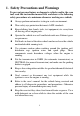
1. Safety Precautions and Warnings To prevent personal injury or damage to vehicles and/or the scan tool, read this instruction manual first and observe the following safety precautions at a minimum whenever working on a vehicle: Always perform automotive testing in a safe environment. Wear safety eye protection that meets ANSI standards. Keep clothing, hair, hands, tools, test equipment, etc. away from all moving or hot engine parts.
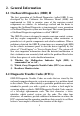
2. General Information 2.1 On-Board Diagnostics (OBD) II The first generation of On-Board Diagnostics (called OBD I) was developed by the California Air Resources Board (ARB) and implemented in 1988 to monitor some of the emission control components on vehicles. As technology evolved and the desire to improve the On-Board Diagnostic system increased, a new generation of On-Board Diagnostic system was developed. This second generation of On-Board Diagnostic regulations is called "OBD II".
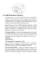
2.3 Location of the Data Link Connector (DLC) The DLC (Data Link Connector or Diagnostic Link Connector) is the standardized 16-cavity connector where diagnostic scan tools interface with the vehicle's on-board computer. The DLC is usually located 12 inches from the center of the instrument panel (dash), under or around the driver‟s side for most vehicles. If Data Link Connector is not located under the dashboard, a label should be there telling the location.
2.4 OBD II Readiness Monitors An important part of a vehicle‟s OBD II system is the Readiness Monitors, which are indicators used to find out if all of the emissions components have been evaluated by the OBD II system. They are running periodic tests on specific systems and components to ensure that they are performing within the allowable limits. Currently, there are eleven OBD II Readiness Monitors (or I/M Monitors) defined by the U.S. Environmental Protection Agency (EPA).
type engines, the available monitors are different too. The following monitors are to be used for spark ignition engines only: 1) 2) 3) 4) 5) 6) 7) EGR System O2 Sensors Catalyst Evaporative System O2 Sensor Heater Secondary air Heated Catalyst The following monitors are to be used for compression ignition engines only: 1) 2) 3) 4) 5) 6) EGR System NMHC Catalyst NOx after treatment Boost pressure system Exhaust gas sensor PM filter 2.
including erasing of diagnostic trouble codes (DTCs) with a scan tool or a disconnected battery, can result in Readiness Monitors being set to “Not Ready”. Since the three continuous monitors are constantly evaluating, they will be reported as “Ready” all of the time. If testing of a particular supported non-continuous monitor has not been completed, the monitor status will be reported as “Not Complete” or “Not Ready.
enabling criteria. Drive cycles vary among vehicles and for each monitor in any particular vehicle. OBD II Drive Cycle -- A specific mode of vehicle operation that provides conditions required to set all the readiness monitors applicable to the vehicle to the “ready” condition. The purpose of completing an OBD II drive cycle is to force the vehicle to run its onboard diagnostics.
but it was captured and stored when a malfunction occurred and a DTC was set. Some of the PIDs for mode one are not implemented in this mode. Mode $03 – Displays the type of power-train or emission related DTCs stored by a 5 digit code identifying the faults. There may be more than one response message if there are more trouble codes than will fit in the data bytes of the response message, or if there are more than one ECU computer responding. Mode $04 – Used to clear DTCs and Freeze Frame data.
properly after diagnostic trouble codes are cleared. Mode $08 – This special Control Mode requests control of the on-board system, test, or component bi-directionally (where applicable). The mode is manufacturer specific. Mode $09 – Reports vehicle information. This information includes vehicle VIN number and calibration information stored in the vehicle ECUs. Mode $0A – Request Emission-Related Diagnostic Trouble Codes with Permanent Status. This mode is required for all emissions-related DTCs.
3. Using the Scan Tool 3.1 Tool Description 1) OBD II CONNECTOR – Connects the scan tool to the vehicle‟s DLC. 2) LCD DISPLAY – Displays menus and test results. 3) FUNCTION BUTTONS – Corresponds with “buttons” on screen for executing commands.
4) ESC BUTTON – Cancels a selection (or action) from a menu or returns to the previous screen. 5) LEFT SCROLL BUTTON – When scrolling through a screen of data or text moves to previous character and views additional information on the previous screen, if recorded data content covers more than one screen. It is also used to view previous trouble code when viewing DTCs. 6) HELP BUTTON – Provides help information and Code Breaker function.
3.2 Specifications 1) Display: TFT color display (320 x 240 dpi) 2) Operating Temperature: 0 to 60°C (32 to 140 F°) 3) Storage Temperature: -20 to 70°C (-4 to 158 F°) 4) External Power: 8.0 to 18.0 V power provided via vehicle battery 5) Dimensions: 6) Length 7) 199 mm (7.83”) Width 104.5 mm (4.11”) Height 37.5 mm (1.48”) 8) Weight: 0.28kg(without wire) 0.484kg(with wire) 3.3 Accessories Included 1) User’s Manual -- Instructions on the tool‟s operations.
Just follow the steps below to turn on the scan tool: 1) Connect the OBD II Cable to the scan tool. 2) Find DLC on the vehicle. A plastic DLC cover may be found for some vehicles and you need to remove it before plugging the OBDII cable. 3) Plug the OBD II cable to the vehicle‟s DLC. 4) Power up the scan tool, and wait for the Main Screen to appear. (Figure 3.1) Figure 3.1 3.
To enter the Setup menu On Main Screen use the LEFT/RIGHT scroll button to select Setup, and press the OK button. Following the instructions to do adjustments and settings could make your diagnosis more convenient and easy. Figure 3.2 Language Setup English is the default language. 1) On System Setup screen, use the UP/DOWN scroll button and LEFT/RIGHT scroll button to select Language, and press the OK button.
Note: The current version of AL609 scan tool supports only the English language, and there will be more languages to come with new updates released. Unit of Measure Metric is the default measurement unit. 1) On System Setup screen, use the UP/DOWN scroll button and LEFT/RIGHT scroll button to select Unit and press the OK button. 2) Use the LEFT/RIGHT scroll button to select the desired unit of measurement. Figure 3.
Figure 3.5 3) Press the OK button to save your selection and return to the previous menu, or press the ESC button to exit without saving. Key Test The Key Test function checks if the keyboard is working properly. 1) On System Setup screen, use the UP/DOWN scroll button and LEFT/RIGHT scroll button to select Key Test, and press the OK button. 2) Press any key to start test.
LCD Test The LCD Test function checks if the LCD display is working normally. 1) On System Setup screen, use the UP/DOWN scroll button and LEFT/RIGHT scroll button to select LCD Test, and press the OK button. 2) Check if there is any missing spot in the red, green, blue, black and white LCD displays. 3) When the test is completed, press the ESC button to exit. About The About function allows viewing of the important information, such as serial number and software version number of the scan tool.
3.7 Vehicle Coverage The AutoLink AL609 OBDII/EOBD Scanner is specially designed to work with all OBD II compliant vehicles, including those equipped with next-generation protocols -- Control Area Network (CAN). It is required by EPA that all 1996 and newer vehicles (cars and light trucks) sold in the United States must be OBD II compliant and this includes all the US Domestic, Asian and European vehicles. A small number of 1994 and 1995 model year gasoline vehicles are OBD II compliant.
Vehicle Linking Error A communication error occurs if the scan tool fails to communicate with the vehicle‟s Engine Control Unit (ECU). In this case you need to do the followings to check up: Verify whether or not the ignition is ON. Check if the scan tool‟s OBD II connector is securely connected to the vehicle‟s DLC. Verify if the vehicle is OBDII compliant. Turn the ignition off and wait for about 10 seconds. Turn the ignition back to on and continue the testing.
4. ABS Diagnosis ABS -“Anti-lock Braking System” in most vehicles is made up of an electronic hydraulic pump of two, three or most commonly four Wheel Speed Sensors (WSS), a G-force sensor, a Vehicle Speed Sensor and an ABS Control Module (EBCM). The EBCM is constantly monitoring the WSS, the Vehicle Speed Sensor, and the G-sensor. Diagnosing an ABS problem should always start with a visual inspection of all brake components, then you will need to retrieve ABS DTCs to tell you where the problem is.
5) Turn on the scan tool and wait for the Main Screen to appear. 6) Select ABS in the Main Screen. (Figure 3.1) 4.1 Vehicle Selection There are three ways for users to enter the vehicle information in the scan tool. A. Select vehicle step by step In this mode, the scan tool will communicate with the vehicle and a series of vehicle identification screens appears for user to identify the vehicle.
B. Manual vehicle entry This mode allows users to input and save specific vehicle information (i.e. PCM Part Number, Vehicle Calibration Number Tear Tag, and VIN) manually. This function enables direct access to the vehicle‟s ABS system and makes the diagnostic testing more convenient, saving time doing step-by-step entry selections. (Taking Ford as an example) 1) Select the Ford logo from the car make screen. (Figure 4.2) Figure 4.
select one of the three entries in the option screen - PCM Part Number, Calibration Number or Tear Tag - to fill up the vehicle information. Figure 4.4 4) Taking the PCM Part Number entry for example, you will need to fill up the accurate vehicle information in the input entry. Figure 4.5 [ Finish ] : After entering a new value, use this key to save the value to the tool. [ Edit ] : Press this key to pop up a soft keyboard to facilitate your input. (Figure 4.6) [ Esc ] : Press this key to exit.
Figure 4.6 The three keyboard function keys work as below. [ Finish ]: When you finished the input, select this key to confirm your input and exit. [ Pre. ] : Moves a space to the left. [ Backspace ]: Uses this key to erase the previous digit or character when typing. NOTE: The data you input must be in the reasonable range.
C. Auto vehicle entry Some vehicles provide an auto scan feature, which allows user to skip time-wasting step-by-step vehicle identification procedure and retrieve the specific vehicle information from vehicle computer directly. NOTE: This function may not be available for all vehicles. Take Ford as an example. 1) Select the Ford logo from the vehicle make screen. Figure 4.8 2) Use the UP/DOWN scroll button to select the Start New Session from the menu.
Figure 4.9 4.2 Reading ABS Codes This function allows user to read the ABS DTCs from vehicle ECU. 1) Follow 4.1 Vehicle Selection procedure to enter the vehicle information. The scan tool displays a function menu (Figure 4.10).(Taking Fiat as an example) Figure 4.10 2) Use the UP/DOWN scroll button to select Read Codes from Function Menu and press the OK button. 3) View DTCs and their definitions on screen.
Figure 4.11 4) Select Save option to store the codes or press Esc button to exit without saving. 4.3 Erasing ABS Code This function allows user to erase the ABS DTCs in vehicle ECU. NOTE: If you plan to take the vehicle to a Service Center for repair, DO NOT erase the ABS DTCs from the vehicle’s computer. If the codes are erased, valuable information that might help the technician troubleshoot the problem will be erased. 1) Follow 4.1 Vehicle Selection procedure to enter the vehicle information.
Figure 4.12 4) Select Yes to confirm and No to exit. When the command is sent, the tool will display a message. Figure 4.13 5) To make sure the codes are erased completely, perform Read Codes function to verify. 4.4 ECU Information This function allows user to read the vehicle ECU information. 1) Follow 4.1 Vehicle Selection procedure to enter the vehicle information. The scan tool displays a function menu (Figure 4.10).
3) View retrieved vehicle information on screen. Figure 4.14 4) Select Save option to store the codes or press Esc button to exit without saving. If the vehicle does not support ABS communication, an advisory message will show. Follow the onscreen instructions to exit the system.
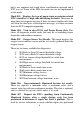
5. OBDII Diagnosis The OBD II Diagnostics function is a fast-access option that allows you to carry out a quick test on the engine system of OBD II vehicles. When more than one vehicle control module is detected by the scan tool, you will be prompted to select the module where the data may be retrieved. The most often to be selected are the Power-train Control Module [PCM] and Transmission Control Module [TCM]. CAUTION: Don’t connect or disconnect any test equipment with ignition on or engine running.
Turn the ignition off and wait for about 10 seconds. Turn the ignition back to on and repeat the procedure from step 5. If the “LINKING ERROR” message does not go away, then there might be problems for the scan tool to communicate with the vehicle. Contact your local distributor or the manufacturer’s customer service department for assistance. 7) View a summary of System Status (MIL status, DTC counts, and Monitor status) onscreen. (Figure 5.1) Press the ESC button and the Diagnostic Menu (Figure 5.
Use the UP/DOWN scroll button to select a module and press the OK button. 5.1 Read Codes Reading Codes can be done with the key on engine off (KOEO) or with the key on engine running (KOER). Stored Codes are also known as “hard codes”, which are fault codes, or trouble codes that have been stored in the vehicle computer memory because the faults have reoccurred for more than a specified amount of key-cycles.
Figure 5.3 2) Use the UP/DOWN scroll button to select Stored Codes, Pending Codes or Permanent Codes from the Read Codes menu and press the OK button. (Figure 5.4) Figure 5.4 If there is not any Diagnostic Trouble Code, the display indicates “No (pending) codes are stored in the module!” Wait a few seconds or press any key to return to the previous screen. NOTE: Permanent Codes function is available for merely vehicles supporting the CAN protocols. 3) View DTCs and their definitions on screen.
If the retrieved DTCs contain any manufacturer specific or enhanced codes, a “Manufacturer specific codes are found! Press any key to select vehicle make!” message comes up prompting you to select the vehicle manufacturer to view the DTC definitions. Use the UP/DOWN scroll button to select the manufacturer and then press the OK button to confirm. Figure 5.5 If the manufacturer of your vehicle is not listed, use the UP/DOWN scroll button to select Other and press the OK button. 5.
1) Use the UP/DOWN scroll buttons to select Erase Codes from Diagnostics Menu and press the OK button. (Figure 5.3) 2) A warning message comes up asking for your confirmation. (Figure 5.6) Figure 5.6 If you do not want to proceed with erasing codes, press the Esc button or select NO to exit and return to the previous screen. 3) Press the OK button to confirm. If the codes are cleared successfully, an “Erase Done!” message shows on the display. Figure 5.
Figure 5.8 4) Press any button to return to Diagnostic Menu. 5.3 Live Data In this function, you can not only read the live data but also record data for later reviews. Viewing Data The View Data function allows viewing of live or real time PID data of vehicle’s computer module(s). 1) To view live data, use the UP/DOWN scroll button to select Live Data from Diagnostic Menu and press the OK button. (Figure 5.3) 2) Wait a few seconds while the scan tool validates the PID MAP.
Figure 5.9 A. Viewing Complete List 1) To view a complete set of data, use the UP/DOWN scroll button to select Complete List from Live Data menu and press the OK button. Figure 5.10 2) To view the live PIDs onscreen, use the UP/DOWN scroll button for all PIDs to display if additional information is available on more than one page. Figure 5.11 If the “One Graphic” at the bottom appears when a PID is highlighted, graphic information is available. Select One Graphic to view the graph. (Figure 5.12).
Figure 5.12 Select Two Graphics to display two graphs on the same screen. (Figure. 5.13) If the “Merge Graph” at the bottom appears, merged graph information is available. (Figure 5.13) NOTE: Merge Graph can be used to compare two related parameters in graphic mode, which is especially convenient in the Custom List option where you could select two interacted parameter to merge and see their relationship. Figure 5.13 Select Text to return to the text viewing mode of PID data.
Select Pause to suspend viewing. You could resume the viewing process again by selecting Start. 3) Press the ESC button to return to the previous menu. B. Viewing Custom List 1) To view customized PID data, use the UP/DOWN scroll button to select Custom List from Live Data menu and press the OK button.( Figure 5.10) 2) Use the UP/DOWN scroll button to move up and down to the desired items and click Select button to confirm. The selected parameters are marked with solid squares. Figure 5.
Figure 5.15 4) Press the ESC button to return to the previous menu. Recording Data The Record Data function allows recording vehicle modules’ Parameter Identification data (PID) to help diagnosing intermittent vehicle problems. You could save data files to the SD card and then use the Playback function to view the saved files. NOTE: The length of time for each frame varies per vehicle. Generally, one frame of data is about 1/4 second, or 4 frames per second.
Figure 5.16 If you record live data under graph mode, following screen shows: Figure 5.17 NOTE: The scan tool can only playback text data even though the data is saved in graphic mode. 2) When there is not enough memory space, a warning message will prompt to ask users to clean up.
Figure 5.18 3) Select OK to return to the previous menu. 4) Select Pause to suspend recording. You could resume the recording process again by selecting Start. 5) Press the ESC button to exit. NOTE: You can review the saved data in Playback function. 5.4 Freeze Frame Freeze Frame Data allows the technician to view the vehicle’s operating parameters at the moment a DTC (Diagnostic Trouble Code) is detected.
3) If the retrieved information covers more than one screen, use the DOWN scroll button as necessary, until all the data have shown up. Figure 5.19 If there is no available freeze frame data, a notice “No freeze frame data stored!” shows on the display. 4) Select Save to record freeze frame. A confirming message “Save success!” will show on the display and return to the previous menu. 5) If you don‟t want to save the freeze frame data, press the ESC button to return. 5.
Some latest vehicle models may support two types of I/M Readiness tests: A. Since DTCs Cleared - indicates status of the monitors since the DTCs are erased. B. This Drive Cycle - indicates status of monitors since the beginning of the current drive cycle. An I/M Readiness Status result of “NO” does not necessarily indicate that the vehicle being tested will fail the state I/M inspection. For some states, one or more such monitors may be allowed to be “Not Ready” to pass the emissions inspection.
4) Use the UP/DOWN scroll button, as necessary, to view the status of the MIL light (“ON” or “OFF) and the following monitors: Malfunction Indicator Lamp Status Misfire Monitor Fuel System Monitor Comprehensive Component Monitor Catalyst Monitor Heated Catalyst Monitor Evaporative System Monitor Secondary Air system Monitor Oxygen Sensor Monitor Oxygen Sensor Heater Monitor EGR System Monitor Figure 5.
Figure 5.22 6) Use the UP/DOWN scroll button for more PIDs if additional information is available on more than one page. Or use the LEFT/RIGHT scroll button to view PIDs in the previous/next page. 7) Press the ESC button to return to Diagnostic Menu. 5.6 O2 Monitor Test OBDII regulations set by SAE require that relevant vehicles monitor and tests on the oxygen (O2) sensors to identify problems related to fuel efficiency and vehicle emissions.
2) Wait a few seconds while the scan tool validates the PID MAP. 3) Use the UP/DOWN scroll button to select O2 sensor from O2 Monitor Test menu and the press OK button. Figure 5.23 If the vehicle does not support the mode, an advisory message will be displayed on the screen. Figure 5.24 4) View test results of the selected O2 sensor. (Figure 5.
Figure 5.25 5) Use the UP/DOWN scroll button to view more data if additional information is available in more than one page. 6) Press the ESC button to return to the previous menu. 5.7 On-Board Monitor Test The On-Board Monitor Test is useful after servicing or after erasing a vehicle’s control module memory. The On-Board Monitor Test for non-CAN-equipped vehicles retrieves and displays test results for emission-related power train components and systems that are not continuously monitored.
2) Wait a few seconds while the scan tool validates the PID MAP. 3) The scan tool will prompt you to select the vehicle make. (If you have selected the vehicle before, the Vehicle Manufacturer screen would not appear again.) Figure 5.26 4) After selecting the vehicle manufacturer, the scan tool shows the On-Board Monitors tests for the specific monitoring systems. 5) On On-Board Monitor Test menu, use the UP/DOWN scroll button to select a test to view and press the OK button. Figure 5.
Figure 5.28 For CAN-equipped vehicles, test selections can be as below: Figure 5.29 6) Use the UP/DOWN scroll button to select the desired monitor from On-Board Monitor Test menu and press the OK button. 7) View test data on screen. Figure 5.
For CAN-equipped vehicles, test results displayed can be as below: Figure 5.31 8) Press the ESC button to return to the previous menus. 5.8 Component Test The Component Test function allows initiating a leak test for the vehicle's EVAP system. The scan tool itself does not perform the leak test, but commands the vehicle's on-board computer to start the test. Different vehicle manufacturers might have different criteria and methods for stopping the test once it has been started.
Figure 5.32 3) If the test has been initiated by the vehicle, a confirmation message will be displayed on the screen. Figure 5.33 Some vehicles do not allow scan tools to control vehicle systems or components. If the vehicle under test does not support the EVAP Leak Test, an advisory message is displayed on the screen. Figure 5.
4) Wait a few seconds or press any key to return to the previous screen. 5.9 Viewing Vehicle Information The Vehicle Information function enables retrieval of Vehicle Identification No. (VIN), Calibration ID Nos. (CINs), Calibration Verification Nos. (CVNs) and In-use Performance Tracking on 2000 and newer vehicles that support Mode 9. 1) Use the UP/DOWN scroll button to select Vehicle Info on the Diagnostic Menu and press the OK button. (Figure 5.
If the vehicle does not support this mode, a message shows on the display warning that the mode is not supported. 4) From Vehicle Info menu, use the UP/DOWN scroll button to select an available item to view and press the OK button. 5) View the retrieved vehicle information. Figure 5.37 6) Press the ESC button to return the previous menu 5.10 Modules Present The Modules Present function allows viewing of the module IDs and communication protocols for OBDII modules in the vehicle.
Figure 5.38 3) Select Save to save the modules data and return to the previous menu, or press the ESC button to exit. 5.11 DTC Lookup The DTC Lookup function allows user to search definitions of the DTCs stored in the built-in DTC library. 1) Use the UP/DOWN scroll button to select DTC Lookup from Diagnostic Menu and press the OK button. (Figure 5.3) 2) Wait for the scan tool to display the DTC Lookup screen. Figure 5.39 3) Select Show and a soft keyboard will pop up.
input. Select „Backspace‟ to erase the previous digit or character, and/or „Pre.‟ to move a space to the left for editing. Figure 5.40 4) After entering the DTC code, select Finish and a message will show to ask for your confirmation to save the DTC item. Figure 5.41 5) Press Yes or the OK button to proceed. The scan tool will display the designated DTC‟s definition.
Figure 5.42 Use the LEFT/RIGHT scroll button to view the previous/next DTC. Select Save to record the code‟s definition. For manufacturer specific codes, you need to select a vehicle make on an additional screen to look for DTC definitions. If definition could not be found (SAE or Manufacturer Specific), the scan tool displays “Please refer to vehicle service manual!” 6) Press No or the ESC button to return to the previous menu.
6. Playback The Playback Data function allows reviews for data recorded by the scan tool from vehicle tests. 6.1 Data Viewing 1) Use the LEFT/RIGHT scroll button to select Playback from Main Screen (Figure 3.1), and press the OK button. Wait for the Review Data menu to appear. Figure 6.1 2) To review data saved in the OBDII diagnosis function, select OBDII from the menu. To review data saved in the ABS diagnosis function, select ABS from the menu, and then press the OK button to continue. Figure 6.
3) Use the UP/DOWN scroll button to select the desired item for detailed information from the OBDII menu or the ABS menu, and press the OK button to continue. Figure 6.3 4) Select Print to upload the recorded data to your computer for printing, or press the ESC button to exit. NOTE: For operation details of data printing, see 7.1 Print Data. 6.2 Data Deleting By selecting Delete on the data screen users can erase the selected data on the scan tool. Review the recordings thoroughly before erasing.
7. Print and Update 7.1. Print Data The Print Data function allows printing out diagnostic data recorded by the scan tool or customized test reports by connecting the scan tool to a PC or laptop with the USB cable supplied. To print out the retrieved data, you need the followings: AL609 scan tool A PC or laptop with USB ports A USB cable 1) Install the PC Suite through the included CD, or download the applications in our website: www.maxidas.com or our distributors‟ site.
Figure 7.1 7) The selected data will display on the textbox of Printer. By selecting the function keys on the right, you could execute the following operations: Print – Print all data in the textbox with the printer connected to the PC. Edit – Once clicked, the software will automatically open a NOTEPAD window with all recorded data for editing. Copy – Copy all data in the textbox to the clipboard. Clear – Delete all data in the textbox. Exit – Quit the operation.
tool on our website: www.maxidas.com. Then you could download software, update online, retrieve information and get warranty service. NOTE: Prior to registration, please confirm your network is working properly. 1. Visit our website www.maxidas.com. 2. Click on the Update tool bar at the top of the screen, and then select User Register, or click on the Updates column in the lower right corner of the screen, and select Register. 3. The screen of Register Information appears.
Update Procedure Autel frequently releases software updates that you can download. The Update feature makes it very easy to determine and get exactly what you need. 1) Install the PC Suite through the included CD, or download the applications in our website: www.maxdas.com or our distributors‟ site. 2) Make sure that your PC is connected to the Internet. 3) Remove the TF card from the scan tool. 4) Connect the TF card to the PC with a card reader.
Figure 7.4 Generally, there are two ways to update programs: Batch updating Select the programs that you would update by clicking on the check boxes next to those items. Then click the Update Selected Items button on the right side of screen. Or click on the Select All checkbox on the right side of screen and all updatable items will be selected automatically. Then click the Update Selected Items button on the right side of screen.
Single updating Find out the desired updating item and click the INSTALL button in the same line, and the INSTALL button changes to STOP at the same time. Check the updating process by observing the upper left progress bar [downloading] and upper right progress bar [installing]. You may also find progress information in the Status column of updated items. Anytime you could click the Pause button in the line to suspend this progress, and the state of this item would change to STOPPED.
Figure 7.5 Click on Yes to delete the program(s) selected, or on No to cancel the action. The deleted program will automatically add to the end of program list in the UPDATE page in case you would like to install again.
8. Warranty and Service 8.1. Limited One Year Warranty Autel warrants to its customers that this product will be free from all defects in materials and workmanship for a period of one (1) year from the date of the original purchase, subject to the following terms and conditions: 1) The sole responsibility of Autel under the Warranty is limited to either the repair or, at the option of Autel, replacement of the scan tool at no charge with Proof of Purchase. The sales receipt may be used for this purpose.