
User Manual
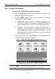
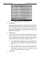

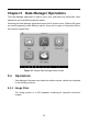
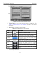
Table Of Contents
- Trademarks
- Copyright Information
- Disclaimer of Warranties and Limitation of Liabilities
- For Services and Support:
- Safety Information
- Contents
- Chapter 1 Using This Manual
- Chapter 2 General Introduction
- Chapter 3 Getting Started
- Chapter 4 Diagnostics Operations
- Chapter 5 Data Manager Operations
- Chapter 6 MaxiFix Operations
- 6.1 Navigation
- The Header
- Select Vehicle Button
- The “Select Vehicle” button on the Header allows you to specify the vehicle which you want to reference on MaxiFix, by selecting each of the vehicle attribute from a sequence of option lists. This feature helps to filter out the searches that allow on...
- 6.1.1 Terminology
- 6.2 Operations
- 6.1 Navigation
- Chapter 7 Settings Operations
- Chapter 8 Shop Manager Operations
- Chapter 9 Update Operations
- Chapter 10 VCI Manager Operations
- Chapter 11 Remote Desk Operations
- Chapter 12 Support Operations
- Chapter 13 Training Operations
- Chapter 14 Quick Link Operations
- Chapter 15 MaxiScope Operations
- 15.1 Safety Information
- 15.2 Glossary
- 15.3 MaxiScope Module
- 15.4 Screen Layout and Operations
- 15.4.1 Top Toolbar
- Math Channel
- A math channel is virtual channel generated by mathematical function of the input channel. It can be displayed in a scope or XY view in the same way as an input signal, and like an input signal it has its own measure axis, scaling and color. The MaxiS...
- Probe
- A probe is any transducer, measuring device or other accessory that you connect to an input channel of your MaxiScope module.
- Reference Waveform
- Recall Reference
- 15.4.2 Functional Buttons
- 15.4.3 Measurement Grid
- 15.4.4 Measurement Rulers
- 15.4.5 Functional Buttons
- 15.4.1 Top Toolbar
- 15.5 Troubleshooting
- 15.6 MaxiScope Firmware Update
- Chapter 16 Digital Inspection Operations
- Chapter 17 Maintenance and Service
- Chapter 18 Compliance Information
- Chapter 19 Warranty

Diagnostics Operations Generic OBD II Operations
58
In most cases the stored frame is the last DTC that occurred. Certain
DTCs, those that have a greater impact on vehicle emission, have a
higher priority. In these cases, the highest priority DTC is the one for
which the freeze frame records are retained. Freeze frame data includes
a “snapshot” of critical parameter values at the time the DTC is set.
Erase Codes
This option is used to clear all emission related diagnostic data such as,
DTCs, freeze frame data and manufacturer specific enhanced data from
the vehicle’s ECM, and resets the I/M Readiness Monitor Status for all
vehicle monitors to Not Ready or Not Complete status.
A confirmation screen displays when the clear codes option is selected to
prevent accidental loss of data. Select Yes on the confirmation screen to
continue, or No to exit.
I/M Readiness
This function is used to check the readiness of the monitoring system. It is an
excellent function to use prior to having a vehicle inspected for compliance to
a state emissions program. Selecting I/M Readiness opens a submenu with
two choices:
Since DTCs Cleared – displays the status of monitors since the last time
the DTCs are erased.
This Driving Cycle – displays the status of monitors since the beginning
of the current drive cycle.
Live Data
This function displays the real time PID data from ECU. Displayed data
includes analog inputs and outputs, digital inputs and outputs, and system
status information broadcast on the vehicle data stream.
Live data can be displayed in various modes, see 4.6.4 Live Data on page 41
for detailed information.
O2 Sensor Monitor
This option allows retrieval and viewing of O2 sensor monitor test results for
the most recently performed tests from the vehicle’s on-board computer.
The O2 Sensor Monitor test function is not supported by vehicles which
communicate using a controller area network (CAN). For O2 Sensor Monitor
tests results of CAN-equipped vehicles, refer to On-Board Monitor..