
User Manual
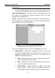
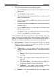
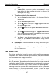
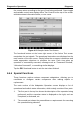
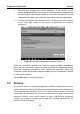
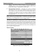
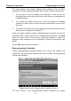
Table Of Contents
- Trademarks
- Copyright Information
- Disclaimer of Warranties and Limitation of Liabilities
- For Services and Support:
- Safety Information
- Contents
- Chapter 1 Using This Manual
- Chapter 2 General Introduction
- Chapter 3 Getting Started
- Chapter 4 Diagnostics Operations
- Chapter 5 Data Manager Operations
- Chapter 6 MaxiFix Operations
- 6.1 Navigation
- The Header
- Select Vehicle Button
- The “Select Vehicle” button on the Header allows you to specify the vehicle which you want to reference on MaxiFix, by selecting each of the vehicle attribute from a sequence of option lists. This feature helps to filter out the searches that allow on...
- 6.1.1 Terminology
- 6.2 Operations
- 6.1 Navigation
- Chapter 7 Settings Operations
- Chapter 8 Shop Manager Operations
- Chapter 9 Update Operations
- Chapter 10 VCI Manager Operations
- Chapter 11 Remote Desk Operations
- Chapter 12 Support Operations
- Chapter 13 Training Operations
- Chapter 14 Quick Link Operations
- Chapter 15 MaxiScope Operations
- 15.1 Safety Information
- 15.2 Glossary
- 15.3 MaxiScope Module
- 15.4 Screen Layout and Operations
- 15.4.1 Top Toolbar
- Math Channel
- A math channel is virtual channel generated by mathematical function of the input channel. It can be displayed in a scope or XY view in the same way as an input signal, and like an input signal it has its own measure axis, scaling and color. The MaxiS...
- Probe
- A probe is any transducer, measuring device or other accessory that you connect to an input channel of your MaxiScope module.
- Reference Waveform
- Recall Reference
- 15.4.2 Functional Buttons
- 15.4.3 Measurement Grid
- 15.4.4 Measurement Rulers
- 15.4.5 Functional Buttons
- 15.4.1 Top Toolbar
- 15.5 Troubleshooting
- 15.6 MaxiScope Firmware Update
- Chapter 16 Digital Inspection Operations
- Chapter 17 Maintenance and Service
- Chapter 18 Compliance Information
- Chapter 19 Warranty

Diagnostics Operations Diagnosis
46
To set threshold limits for the parameter values
1. Tap the Setting functional button at the bottom of the Live
Data screen.
2. Tap the Range navigation button.
3. Select a parameter item on the left column, or enter the item
name in the Search bar.
4. Tap on the right side of the MIN button, and enter the required
minimum value.
5. Tap on the right side of the MAX button, and enter the required
maximum value.
6. Tap the ON/OFF button on the right side of the Buzzer Alarm
button to turn it on or off.
7. Tap Done to save the setting and return to the Live Data
screen; or tap Cancel to exit without saving.
If the threshold limits are successfully set, two horizontal lines now
appear on each of the data graphs (when Waveform Graph Mode is
applied) to indicate the alarming point. The threshold lines are shown in
different colors than the waveform of the parameters for distinction.
Record Button – displays the configuration screen for Record
Setting, on which you can set the trigger type, duration and trigger
point for the data recording function.
a) Trigger Type – sets the trigger mode for data recording,
mainly of two kinds: Manual and Auto. There are four options
available:
1) Manual – allows you to manually start and stop data
recording
2) DTC – auto triggers data recording when any DTC is
detected
3) DTC Check Mode – auto triggers data recording when
certain pre-selected DTC types are detected
4) Parameter – auto triggers data recording when any
parameter value reaches the preset threshold
b) Duration – sets the recording time (for Auto trigger mode