
User Manual
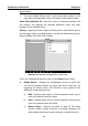
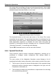
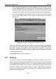
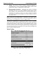
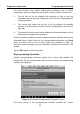
Table Of Contents
- Trademarks
- Copyright Information
- Disclaimer of Warranties and Limitation of Liabilities
- For Services and Support:
- Safety Information
- Contents
- Chapter 1 Using This Manual
- Chapter 2 General Introduction
- Chapter 3 Getting Started
- Chapter 4 Diagnostics Operations
- Chapter 5 Data Manager Operations
- Chapter 6 MaxiFix Operations
- 6.1 Navigation
- The Header
- Select Vehicle Button
- The “Select Vehicle” button on the Header allows you to specify the vehicle which you want to reference on MaxiFix, by selecting each of the vehicle attribute from a sequence of option lists. This feature helps to filter out the searches that allow on...
- 6.1.1 Terminology
- 6.2 Operations
- 6.1 Navigation
- Chapter 7 Settings Operations
- Chapter 8 Shop Manager Operations
- Chapter 9 Update Operations
- Chapter 10 VCI Manager Operations
- Chapter 11 Remote Desk Operations
- Chapter 12 Support Operations
- Chapter 13 Training Operations
- Chapter 14 Quick Link Operations
- Chapter 15 MaxiScope Operations
- 15.1 Safety Information
- 15.2 Glossary
- 15.3 MaxiScope Module
- 15.4 Screen Layout and Operations
- 15.4.1 Top Toolbar
- Math Channel
- A math channel is virtual channel generated by mathematical function of the input channel. It can be displayed in a scope or XY view in the same way as an input signal, and like an input signal it has its own measure axis, scaling and color. The MaxiS...
- Probe
- A probe is any transducer, measuring device or other accessory that you connect to an input channel of your MaxiScope module.
- Reference Waveform
- Recall Reference
- 15.4.2 Functional Buttons
- 15.4.3 Measurement Grid
- 15.4.4 Measurement Rulers
- 15.4.5 Functional Buttons
- 15.4.1 Top Toolbar
- 15.5 Troubleshooting
- 15.6 MaxiScope Firmware Update
- Chapter 16 Digital Inspection Operations
- Chapter 17 Maintenance and Service
- Chapter 18 Compliance Information
- Chapter 19 Warranty

Diagnostics Operations Diagnosis
45
graph merge.
To cancel Graph Merge mode, tap the drop-down button on the
right side of the parameter name, and select a data display mode.
Show Selected/Show All – taps this option to exchange between the
two options; one displays the selected parameter items, the other
displays all the available items.
Setting – tapping this button opens a setting screen, which allows you to
set the trigger mode, recording duration, and various threshold values for
data recording, and make other controls.
Figure 4-12 Sample Setting Mode in Live Data
There are 4 navigation buttons on top of the Setting mode screen.
Range Button – displays the configuration screen on which you
can set the threshold values, an upper limit and a lower limit, for
triggering the buzzer alarm. This function is only applied to the
Waveform Graph display mode.
a) MIN – tapping which opens a virtual keyboard, allows you to
enter the required lower limit value
b) MAX – tapping which opens a virtual keyboard, allows you to
enter the required upper limit value
c) Buzzer Alarm – switches the alarm on and off. The alarm
function makes a beep sound as a reminder whenever the
data reading reaches the preset minimum or maximum point