
User Manual
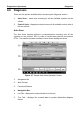
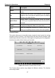
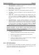
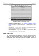
Table Of Contents
- Trademarks
- Copyright Information
- Disclaimer of Warranties and Limitation of Liabilities
- For Services and Support:
- Safety Information
- Contents
- Chapter 1 Using This Manual
- Chapter 2 General Introduction
- Chapter 3 Getting Started
- Chapter 4 Diagnostics Operations
- Chapter 5 Data Manager Operations
- Chapter 6 MaxiFix Operations
- 6.1 Navigation
- The Header
- Select Vehicle Button
- The “Select Vehicle” button on the Header allows you to specify the vehicle which you want to reference on MaxiFix, by selecting each of the vehicle attribute from a sequence of option lists. This feature helps to filter out the searches that allow on...
- 6.1.1 Terminology
- 6.2 Operations
- 6.1 Navigation
- Chapter 7 Settings Operations
- Chapter 8 Shop Manager Operations
- Chapter 9 Update Operations
- Chapter 10 VCI Manager Operations
- Chapter 11 Remote Desk Operations
- Chapter 12 Support Operations
- Chapter 13 Training Operations
- Chapter 14 Quick Link Operations
- Chapter 15 MaxiScope Operations
- 15.1 Safety Information
- 15.2 Glossary
- 15.3 MaxiScope Module
- 15.4 Screen Layout and Operations
- 15.4.1 Top Toolbar
- Math Channel
- A math channel is virtual channel generated by mathematical function of the input channel. It can be displayed in a scope or XY view in the same way as an input signal, and like an input signal it has its own measure axis, scaling and color. The MaxiS...
- Probe
- A probe is any transducer, measuring device or other accessory that you connect to an input channel of your MaxiScope module.
- Reference Waveform
- Recall Reference
- 15.4.2 Functional Buttons
- 15.4.3 Measurement Grid
- 15.4.4 Measurement Rulers
- 15.4.5 Functional Buttons
- 15.4.1 Top Toolbar
- 15.5 Troubleshooting
- 15.6 MaxiScope Firmware Update
- Chapter 16 Digital Inspection Operations
- Chapter 17 Maintenance and Service
- Chapter 18 Compliance Information
- Chapter 19 Warranty

Diagnostics Operations Diagnosis
38
ECU Information – provides the retrieved ECU information in detail.
Selecting opens an information screen.
Read Codes – displays detailed information of DTC records retrieved
from the vehicle control module.
Erase Codes – erases DTC records and other data from the ECM.
Live Data – retrieves and displays live data and parameters from the
vehicle’s ECU.
Active Test – provides specific subsystem and component tests. This
selection may appear as Actuators, Actuator Test, or Function Tests,
etc., and the tests options vary depending on the manufacturer and
model.
Special Functions – provides component adaptation or variant coding
functions for custom configurations, and also allows you to reprogram
adaptive values for certain components after making repairs. Depending
on the test vehicle, this selection may sometimes appear as Control
Unit Adaptations, Variant Coding, Configuration or something similar.
NOTE: With the diagnostic toolbar on top of the screen throughout the whole
diagnostic procedures, you are allowed to make various controls of the
diagnostic information at anytime, such as printing and saving the displayed
data, get help information, or perform data logging, etc.
To perform a diagnostic function
1. Establish communication with the test vehicle via the VCI device.
2. Identify the test vehicle by selecting from the menu options.
3. Select the Diagnosis section.
4. Locate the required system for testing by Auto Scan or through
menu driven selections in Control Units.
5. Select the desired test from the Function Menu.
4.6.1 ECU Information
This function retrieves and displays the specific information for the tested
control unit, including unit type, version numbers and other specifications. The
sample ECU Information screen displays as below: